


Strona 2 z 195.
Copyright
No part of this publication may be reproduced, stored in a retrieval system or transmitted
in any form or by any means, electronic, mechanical, photocopying, recording, scanning or
otherwise, except as permitted under Sections 107 or 108 of the 1976 United States Copyright
Act, without the prior written permission of the publisher or author.
Limit of Liability/Disclaimer of Warranty
The publisher and the author make no representations
or warranties with respect to the accuracy or completeness of the contents of
this work and specifically disclaim all warranties, including without limitation warranties
of fitness for a particular purpose. No warranty may be created or extended by sales or
promotional materials. The advice and strategies contained herein may not be suitable for
every situation. This work is sold with the understanding that the publisher is not engaged
in rendering legal, accounting, or other professional services. If professional assistance is
required, the services of a competent professional person should be sought. Neither the
publisher nor the author shall be liable for damages arising here from. The fact that an
organization or Website is referred to in this work as a citation and/or a potential source of
further information does not mean that the author or the publisher endorses the information
the organization or Website may provide or recommendations it may make. Further,
readers should be aware that Internet Websites listed in this work may have changed or
disappeared between when this work was written and when it is read.
For general information on our other products and services or to obtain technical support,
please email our Customer Care Department contactus@preher-tech.com
2
Strona 3 z 195.
Dedication
This book is dedicated to my wife Lindsay , my daughter Alana and my son Kobin. With out
the support of my wonderful family this book would have never been possible.
I would also like to dedicate this book to Jestine Yong, Author and electronics technician.
Thank you for all your support and inspiration.
3
Strona 4 z 195.
Contents
Liquid Crystals....6
Liquid Crystal Displays....10
The Power Supply Board....15
The Inverter Board....22
The Main Board....26
The Controller/T-Con Board....34
The LCD Driver Board....35
The Standby Circuit....36
The Liquid Crystal Display In Depth....37
Tools....41
Test Equipment....50
Schematic Diagrams....58
Understanding and Testing Resistors....59
Understanding and Testing Capacitors....63
Understanding and Testing Inductors....73
Understanding and Testing Transistors....77
Understanding and Testing Diodes....90
Understanding and Testing Bridge Rectifiers....103
Understanding and Testing LEDs....110
Understanding and Testing Switching Transformers....113
Understanding and Testing Opto-Isolators....117
Understanding and Testing Voltage Regulators....123
Understanding and Testing Switches....126
Understanding and Testing Fuses and Varistors....128
Some Testing Tips....131
Useful Formulas....132
How To Disassemble An LCD TV....133
Voltage Test Points....136
The Tap Test....144
Freeze Spray and Hair Dryers....146
Connection Problems....149
PSU (Power Supply Unit) Failures....152
4
Strona 5 z 195.
Inverter Board Failures....158
Main Board Failures....163
No Video....169
No Audio....171
OSD/Menu Failure....172
White Screen....173
Rainbow Screen....175
Screen Flashes Then TV Shuts Down....176
No Back light....177
Lines In Picture....178
Cracked Panel....179
LCD TV Repair Case Histories....180
Safety....186
Conclusion....190
Further Reading....191
Websites and free download(LCD TV Display Failure Symptoms and
Possible Causes.)....194
Part, Tool and Test Equipment Distributors....195
5
Strona 6 z 195.
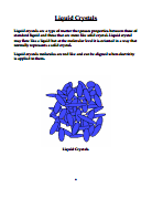
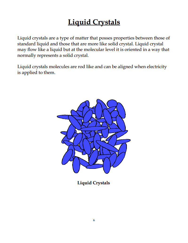
Liquid Crystals
Liquid crystals are a type of matter that posses properties between those of
standard liquid and those that are more like solid crystal. Liquid crystal
may flow like a liquid but at the molecular level it is oriented in a way that
normally represents a solid crystal.
Liquid crystals molecules are rod like and can be aligned when electricity
is applied to them.
Liquid Crystals
6
Strona 7 z 195.
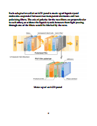
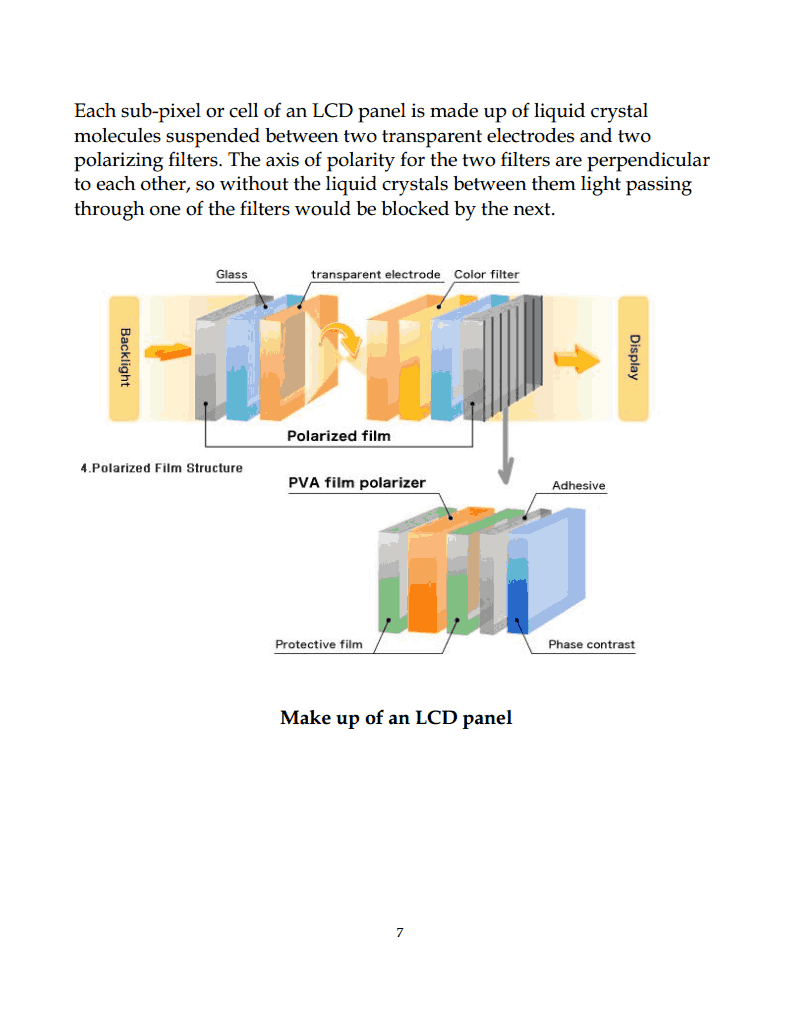
Each sub-pixel or cell of an LCD panel is made up of liquid crystal
molecules suspended between two transparent electrodes and two
polarizing filters. The axis of polarity for the two filters are perpendicular
to each other, so without the liquid crystals between them light passing
through one of the filters would be blocked by the next.
Make up of an LCD panel
7
Strona 8 z 195.
Before an electrical current is applied the molecules are in a “relaxed”
state. When voltage is applied the molecules align themselves with the
electrodes. The electrodes are treated in a manner that causes the crystals
to align in a helical structure. This type is called Twisted Nematic (TN) and
is one of the most common types in LCD TVs.
Twisted nematic (TN)
Twisted nematic displays contain liquid crystal elements which twist and
untwist at varying degrees allowing light to pass through. When no
voltage is applied to a TN liquid crystal cell, the light is polarized to pass
through the cell. In proportion to the voltage applied, the LC cells twist up
to 90 degrees changing the polarization and blocking the light's path. By
properly adjusting the level of the voltage almost any gray level or
transmission can be achieved.
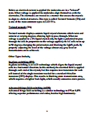
Other Types Include,
In-plane switching (IPS)
In-plane switching is an LCD technology which aligns the liquid crystal
cells in a horizontal direction. In this method, the electrical field is applied
through each end of the crystal, but this requires two transistors for each
cell instead of the single transistor needed for a standard thin-film
transistor (TFT) display. This results in blocking more transmission area,
which requires a brighter back light, which usually consumes more power.
Advanced fringe field switching (AFFS)
Advanced fringe field switching is a similar technology to IPS or S-IPS
offering superior performance and color, besides high luminosity.
8
Strona 9 z 195.
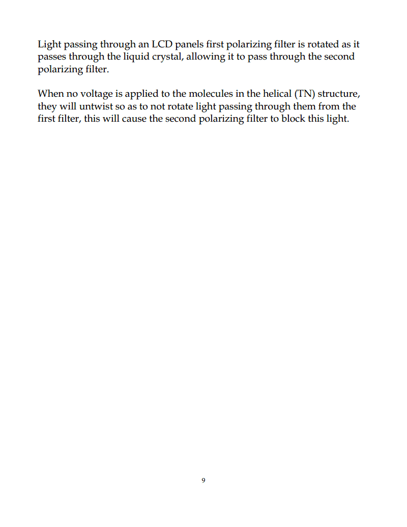
Light passing through an LCD panels first polarizing filter is rotated as it
passes through the liquid crystal, allowing it to pass through the second
polarizing filter.
When no voltage is applied to the molecules in the helical (TN) structure,
they will untwist so as to not rotate light passing through them from the
first filter, this will cause the second polarizing filter to block this light.
9
Strona 10 z 195.
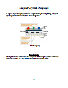
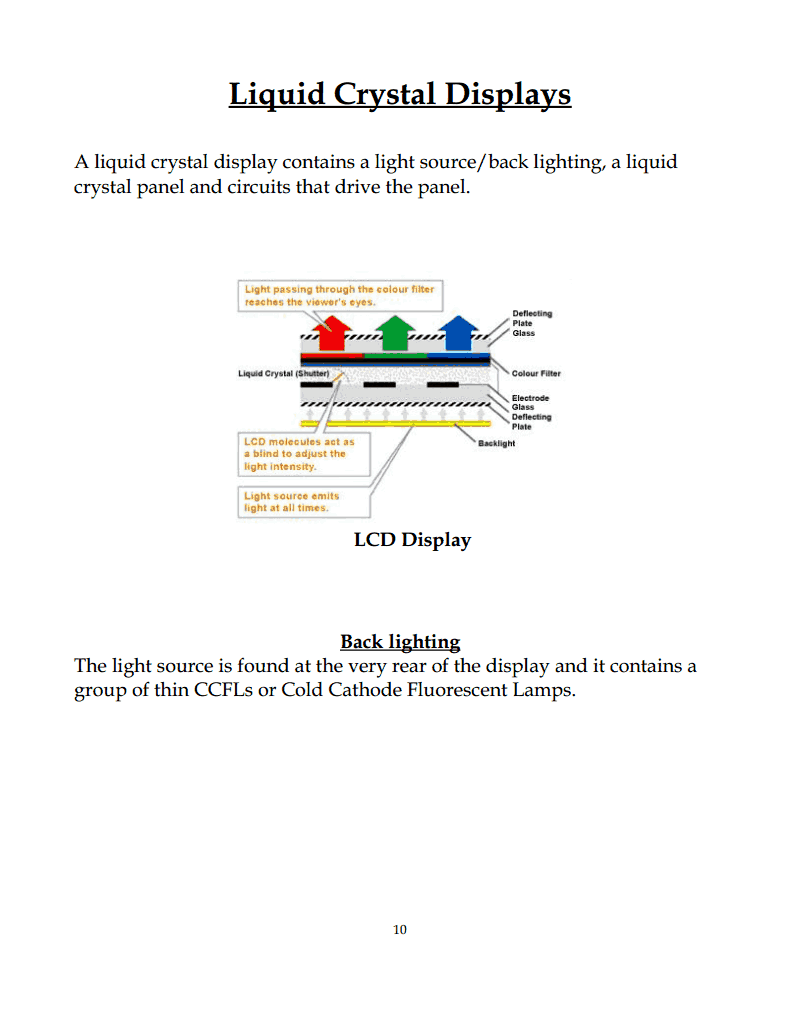
Liquid Crystal Displays
A liquid crystal display contains a light source/back lighting, a liquid
crystal panel and circuits that drive the panel.
LCD Display
Back lighting
The light source is found at the very rear of the display and it contains a
group of thin CCFLs or Cold Cathode Fluorescent Lamps.
10
Strona 11 z 195.
11
Strona 12 z 195.
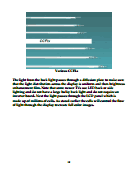
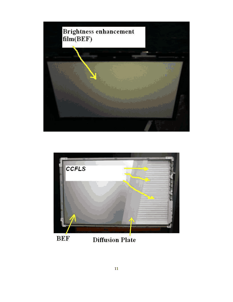
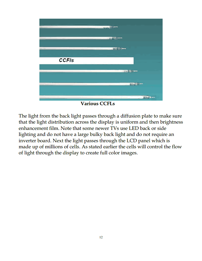
Various CCFLs
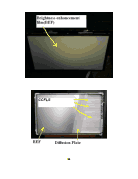
The light from the back light passes through a diffusion plate to make sure
that the light distribution across the display is uniform and then brightness
enhancement film. Note that some newer TVs use LED back or side
lighting and do not have a large bulky back light and do not require an
inverter board. Next the light passes through the LCD panel which is
made up of millions of cells. As stated earlier the cells will control the flow
of light through the display to create full color images.
12
Strona 13 z 195.
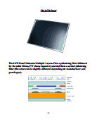
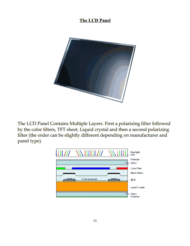
The LCD Panel
The LCD Panel Contains Multiple Layers. First a polarizing filter followed
by the color filters, TFT sheet, Liquid crystal and then a second polarizing
filter (the order can be slightly different depending on manufacturer and
panel type).
13
Strona 14 z 195.
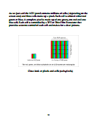
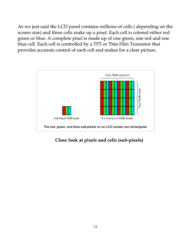
As we just said the LCD panel contains millions of cells ( depending on the
screen size) and three cells make up a pixel. Each cell is colored either red
green or blue. A complete pixel is made up of one green, one red and one
blue cell. Each cell is controlled by a TFT or Thin Film Transistor that
provides accurate control of each cell and makes for a clear picture.
Close look at pixels and cells (sub-pixels)
14
Strona 15 z 195.
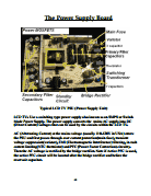
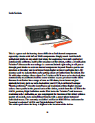
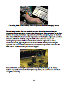
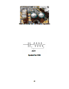
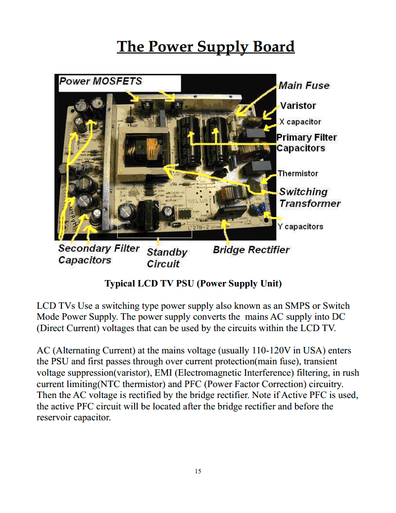
The Power Supply Board
Typical LCD TV PSU (Power Supply Unit)
LCD TVs Use a switching type power supply also known as an SMPS or Switch
Mode Power Supply. The power supply converts the mains AC supply into DC
(Direct Current) voltages that can be used by the circuits within the LCD TV.
AC (Alternating Current) at the mains voltage (usually 110-120V in USA) enters
the PSU and first passes through over current protection(main fuse), transient
voltage suppression(varistor), EMI (Electromagnetic Interference) filtering, in rush
current limiting(NTC thermistor) and PFC (Power Factor Correction) circuitry.
Then the AC voltage is rectified by the bridge rectifier. Note if Active PFC is used,
the active PFC circuit will be located after the bridge rectifier and before the
reservoir capacitor.
15
Strona 16 z 195.
Passive PFC Described
The simplest way to control harmonic current is to use a filter, filters are designed
that pass current only at line frequency (50z or 60 Hz). This filter reduces the
harmonic current, which means that the non-linear device now looks like a linear
load. At this point the power factor can be brought to near unity(1), using
capacitors or inductors as required. This filter requires large value high current
inductors, which are bulky and expensive. Passive PFC needs an inductor larger
than the inductor in an active PFC, but costs less.
Active PFC Described
Active power factor correction (active PFC) uses a more complex electronic
circuit to control the amount of power drawn by a load in order to obtain a power
factor as close as possible to unity(1). Usually the active PFC circuit controls the
input current of the load so that the current waveform is proportional to the mains
voltage waveform (a sine wave). The purpose of making the power factor as close
to unity(1) as possible is to make the circuit that is power factor corrected appear
purely resistive. In this case the voltage and current are in phase and the reactive
power consumption is zero. This allows the most efficient delivery of electrical
power from the power company to the consumer. Some types of active PFC are
Boost,Buck and Buck-boost. Active power factor correction circuits can be single
stage or multistage. In the case of a SMPS, a boost converter is inserted between
the bridge rectifier and the primary side filter capacitor(reservoir capacitor). The
boost converter attempts to maintain a constant DC bus voltage on its output while
drawing a current that is constantly in phase with and at the same frequency as the
line voltage.
The AC voltage Is now Rectified , output from the Bridge rectifier is a pulsed DC
voltage which is then “smoothed” by the reservoir capacitor also called the
primary side filter capacitor.
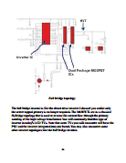
Now let's talk about the power MOSFET/s. In LCD TVs you will commonly find
two power MOSFETs in the typical half bridge topology.
16
Strona 17 z 195.
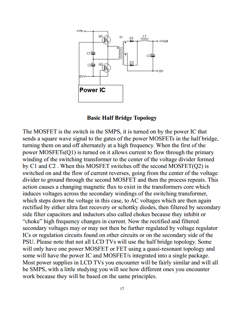
Basic Half Bridge Topology
The MOSFET is the switch in the SMPS, it is turned on by the power IC that
sends a square wave signal to the gates of the power MOSFETs in the half bridge,
turning them on and off alternately at a high frequency. When the first of the
power MOSFETs(Q1) is turned on it allows current to flow through the primary
winding of the switching transformer to the center of the voltage divider formed
by C1 and C2 . When this MOSFET switches off the second MOSFET(Q2) is
switched on and the flow of current reverses, going from the center of the voltage
divider to ground through the second MOSFET and then the process repeats. This
action causes a changing magnetic flux to exist in the transformers core which
induces voltages across the secondary windings of the switching transformer,
which steps down the voltage in this case, to AC voltages which are then again
rectified by either ultra fast recovery or schottky diodes, then filtered by secondary
side filter capacitors and inductors also called chokes because they inhibit or
“choke” high frequency changes in current. Now the rectified and filtered
secondary voltages may or may not then be further regulated by voltage regulator
ICs or regulation circuits found on other circuits or on the secondary side of the
PSU. Please note that not all LCD TVs will use the half bridge topology. Some
will only have one power MOSFET or FET using a quasi-resonant topology and
some will have the power IC and MOSFET/s integrated into a single package.
Most power supplies in LCD TVs you encounter will be fairly similar and will all
be SMPS, with a little studying you will see how different ones you encounter
work because they will be based on the same principles.
17
Strona 18 z 195.
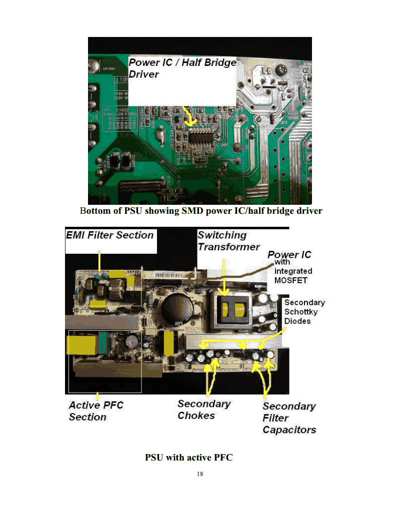
Bottom of PSU showing SMD power IC/half bridge driver
PSU with active PFC
18
Strona 19 z 195.
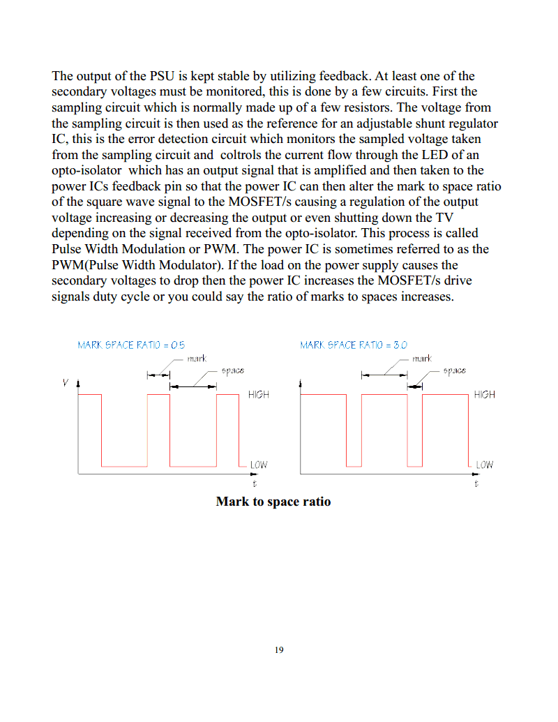
The output of the PSU is kept stable by utilizing feedback. At least one of the
secondary voltages must be monitored, this is done by a few circuits. First the
sampling circuit which is normally made up of a few resistors. The voltage from
the sampling circuit is then used as the reference for an adjustable shunt regulator
IC, this is the error detection circuit which monitors the sampled voltage taken
from the sampling circuit and coltrols the current flow through the LED of an
opto-isolator which has an output signal that is amplified and then taken to the
power ICs feedback pin so that the power IC can then alter the mark to space ratio
of the square wave signal to the MOSFET/s causing a regulation of the output
voltage increasing or decreasing the output or even shutting down the TV
depending on the signal received from the opto-isolator. This process is called
Pulse Width Modulation or PWM. The power IC is sometimes referred to as the
PWM(Pulse Width Modulator). If the load on the power supply causes the
secondary voltages to drop then the power IC increases the MOSFET/s drive
signals duty cycle or you could say the ratio of marks to spaces increases.
Mark to space ratio
19
Strona 20 z 195.
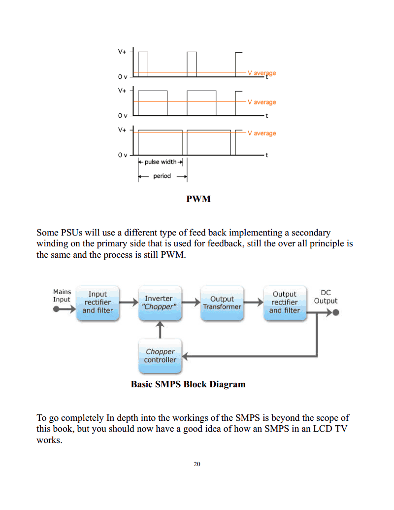
PWM
Some PSUs will use a different type of feed back implementing a secondary
winding on the primary side that is used for feedback, still the over all principle is
the same and the process is still PWM.
Basic SMPS Block Diagram
To go completely In depth into the workings of the SMPS is beyond the scope of
this book, but you should now have a good idea of how an SMPS in an LCD TV
works.
20
Strona 21 z 195.
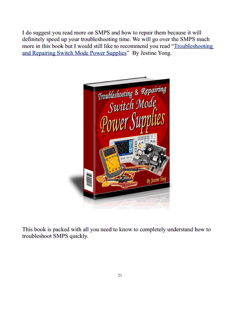
I do suggest you read more on SMPS and how to repair them because it will
definitely speed up your troubleshooting time. We will go over the SMPS much
more in this book but I would still like to recommend you read “Troubleshooting
and Repairing Switch Mode Power Supplies” By Jestine Yong.
This book is packed with all you need to know to completely understand how to
troubleshoot SMPS quickly.
21
Strona 22 z 195.
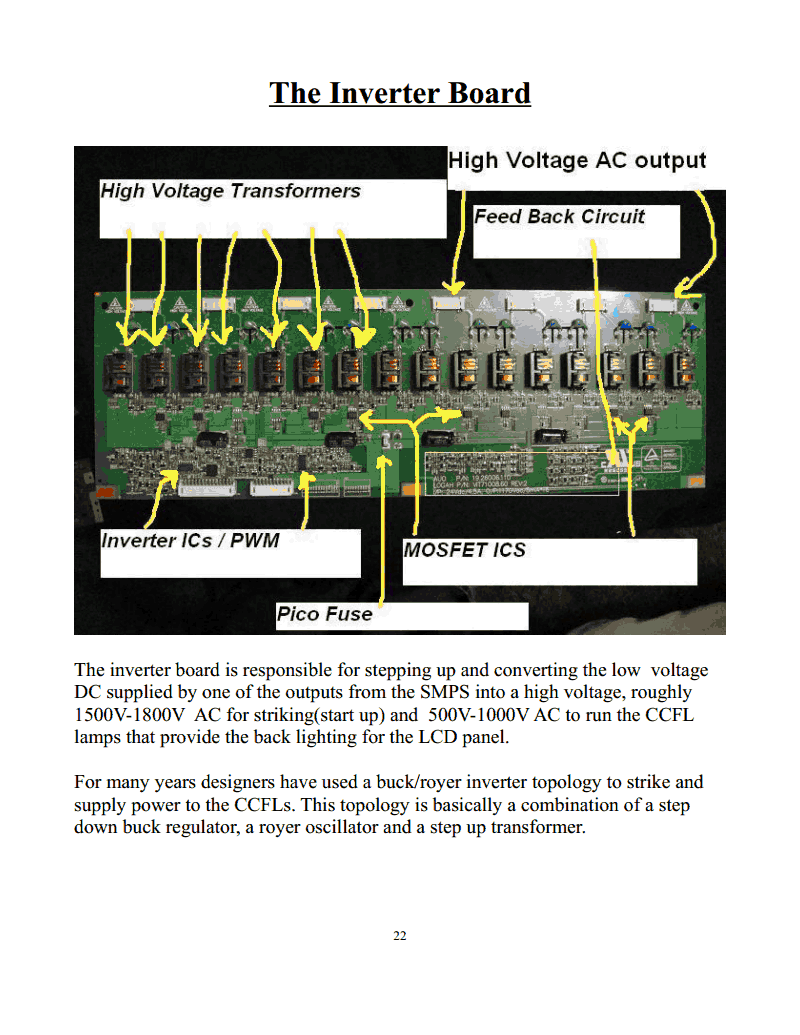
The Inverter Board
The inverter board is responsible for stepping up and converting the low voltage
DC supplied by one of the outputs from the SMPS into a high voltage, roughly
1500V-1800V AC for striking(start up) and 500V-1000V AC to run the CCFL
lamps that provide the back lighting for the LCD panel.
For many years designers have used a buck/royer inverter topology to strike and
supply power to the CCFLs. This topology is basically a combination of a step
down buck regulator, a royer oscillator and a step up transformer.
22
Strona 23 z 195.
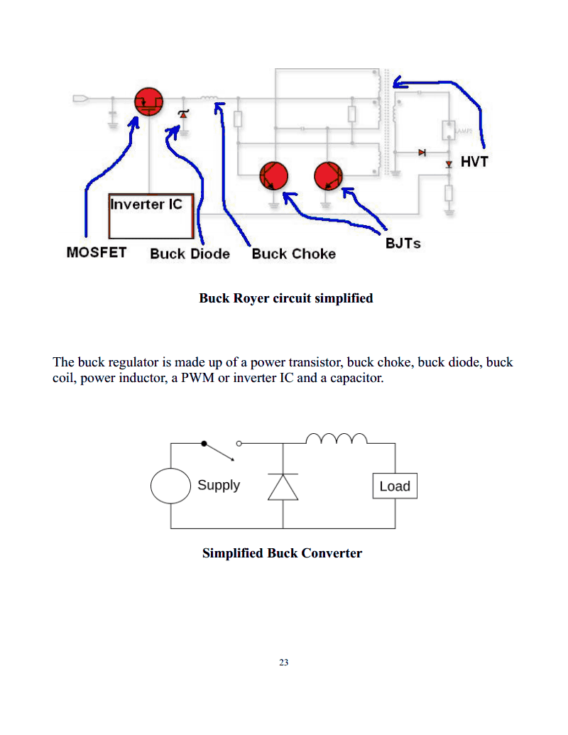
Buck Royer circuit simplified
The buck regulator is made up of a power transistor, buck choke, buck diode, buck
coil, power inductor, a PWM or inverter IC and a capacitor.
Simplified Buck Converter
23
Strona 24 z 195.
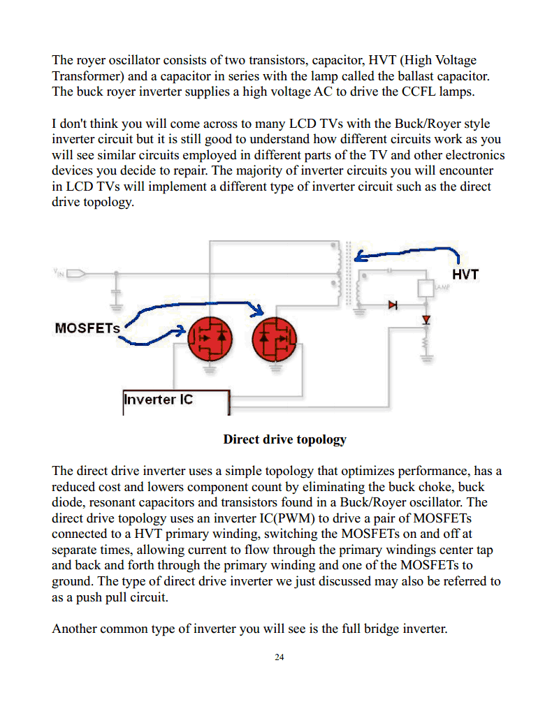
The royer oscillator consists of two transistors, capacitor, HVT (High Voltage
Transformer) and a capacitor in series with the lamp called the ballast capacitor.
The buck royer inverter supplies a high voltage AC to drive the CCFL lamps.
I don't think you will come across to many LCD TVs with the Buck/Royer style
inverter circuit but it is still good to understand how different circuits work as you
will see similar circuits employed in different parts of the TV and other electronics
devices you decide to repair. The majority of inverter circuits you will encounter
in LCD TVs will implement a different type of inverter circuit such as the direct
drive topology.
Direct drive topology
The direct drive inverter uses a simple topology that optimizes performance, has a
reduced cost and lowers component count by eliminating the buck choke, buck
diode, resonant capacitors and transistors found in a Buck/Royer oscillator. The
direct drive topology uses an inverter IC(PWM) to drive a pair of MOSFETs
connected to a HVT primary winding, switching the MOSFETs on and off at
separate times, allowing current to flow through the primary windings center tap
and back and forth through the primary winding and one of the MOSFETs to
ground. The type of direct drive inverter we just discussed may also be referred to
as a push pull circuit.
Another common type of inverter you will see is the full bridge inverter.
24
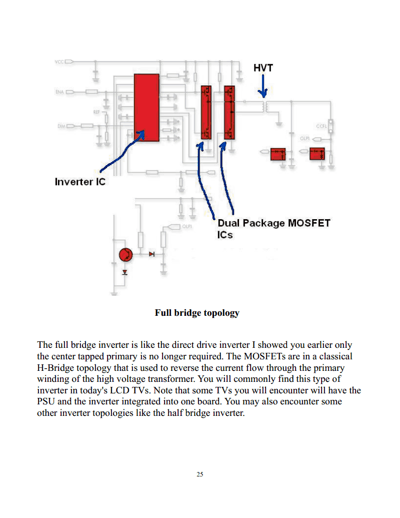
Strona 25 z 195.
Full bridge topology
The full bridge inverter is like the direct drive inverter I showed you earlier only
the center tapped primary is no longer required. The MOSFETs are in a classical
H-Bridge topology that is used to reverse the current flow through the primary
winding of the high voltage transformer. You will commonly find this type of
inverter in today's LCD TVs. Note that some TVs you will encounter will have the
PSU and the inverter integrated into one board. You may also encounter some
other inverter topologies like the half bridge inverter.
25
Strona 26 z 195.
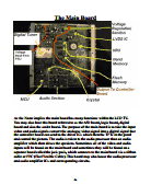
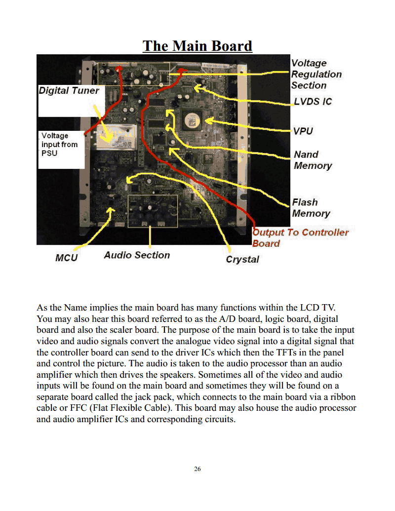
The Main Board
As the Name implies the main board has many functions within the LCD TV.
You may also hear this board referred to as the A/D board, logic board, digital
board and also the scaler board. The purpose of the main board is to take the input
video and audio signals convert the analogue video signal into a digital signal that
the controller board can send to the driver ICs which then the TFTs in the panel
and control the picture. The audio is taken to the audio processor than an audio
amplifier which then drives the speakers. Sometimes all of the video and audio
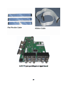
inputs will be found on the main board and sometimes they will be found on a
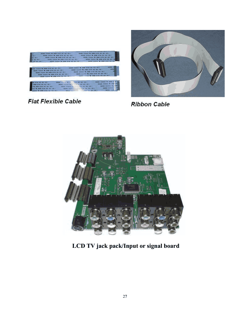
separate board called the jack pack, which connects to the main board via a ribbon
cable or FFC (Flat Flexible Cable). This board may also house the audio processor
and audio amplifier ICs and corresponding circuits.
26
Strona 27 z 195.
LCD TV jack pack/Input or signal board
27
Strona 28 z 195.
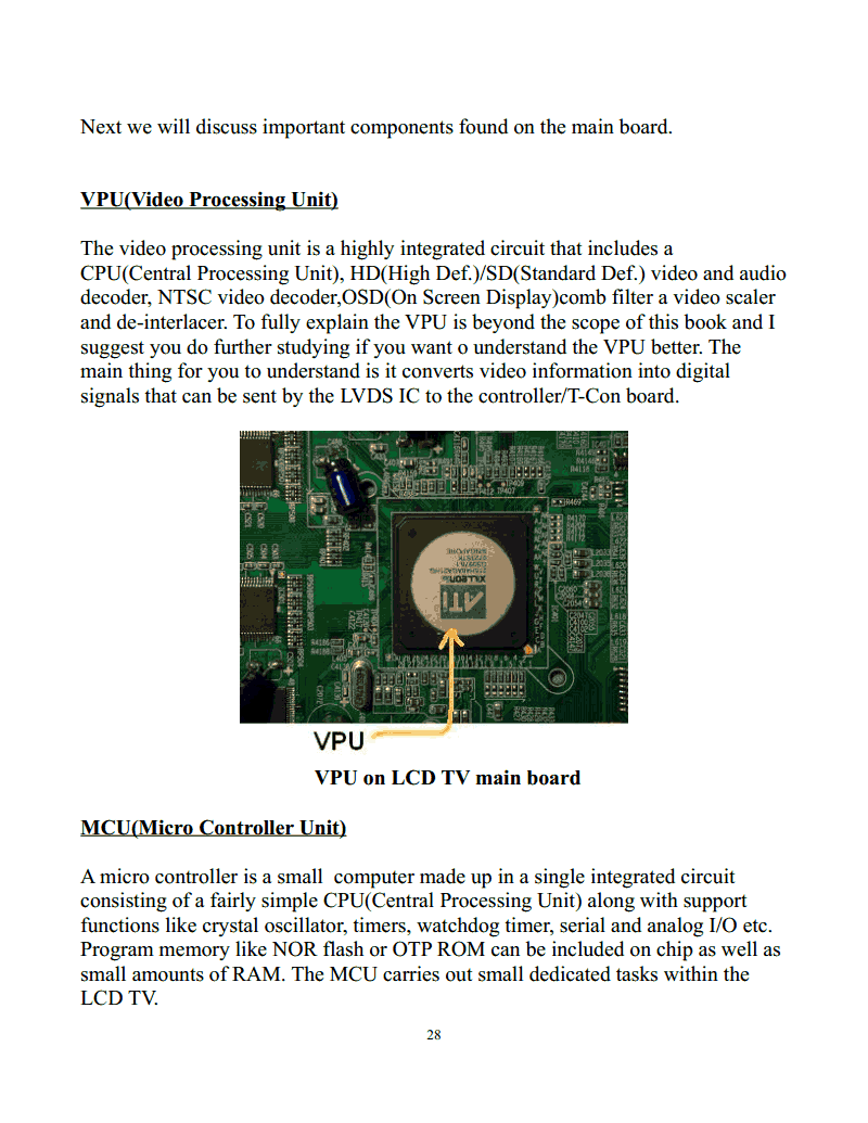
Next we will discuss important components found on the main board.
VPU(Video Processing Unit)
The video processing unit is a highly integrated circuit that includes a
CPU(Central Processing Unit), HD(High Def.)/SD(Standard Def.) video and audio
decoder, NTSC video decoder,OSD(On Screen Display)comb filter a video scaler
and de-interlacer. To fully explain the VPU is beyond the scope of this book and I
suggest you do further studying if you want o understand the VPU better. The
main thing for you to understand is it converts video information into digital
signals that can be sent by the LVDS IC to the controller/T-Con board.
VPU on LCD TV main board
MCU(Micro Controller Unit)
A micro controller is a small computer made up in a single integrated circuit
consisting of a fairly simple CPU(Central Processing Unit) along with support
functions like crystal oscillator, timers, watchdog timer, serial and analog I/O etc.
Program memory like NOR flash or OTP ROM can be included on chip as well as
small amounts of RAM. The MCU carries out small dedicated tasks within the
LCD TV.
28
Strona 29 z 195.
MCU on LCD TV main board
EEPROM(Electronically Erasable Programmable Read Only Memory)
EEPROMs are a type of non-volatile memory used in electronic devices. Just as
the name implies an EEPROM can be erased and programmed with electrical
signals. EEPROMs are used to store information such as user adjustable settings
and preferences among other things. When you make for instance a brightness
adjustment the MCU may store this information in an external EEPROM.
EEPROMS on LCD TV main board
29
Strona 30 z 195.
Voltage Regulator ICs
Voltage regulator ICs provide a constant stable voltage for the ICs and other
circuits found on the main board.
Flash Memory
Flash memory is non-volatile and it is a specific type of EEPROM that is erased
and programmed in large blocks. Flash memory costs much less than byte-
programmable memory EEPROM and so is dominant wherever a large amount of
non-volatile memory is needed. The LCD TV software is usually stored on flash
memory and this software can sometimes be upgraded through a USB port or
memory card reader on your TV.
30
Strona 31 z 195.
Audio Processor
The audio processor receives digital and analogue audio signals input to the TV
and converts them into a signal that can be used by the audio amplifier to drive the
speakers and also to decode and send audio to peripheral devices.
Audio Amplifier
The audio amplifier as the name implies is responsible for receiving the signal
from the output of the audio processor which is small in amplitude and using it to
drive a signal with larger amplitude but the same modulations through the TV
speakers.
31
Strona 32 z 195.
LVDS(Low Voltage Differential Signaling)IC
The LVDS IC uses low voltage differential signaling to send the video signal from
the main board to the T-Con/LCD controller board . LVDS is a differential
signaling system, meaning that it transmits two different voltages that are
compared at the receiving end. LVDS uses this difference in voltage to encode the
video signal.
32
Strona 33 z 195.
Crystals
The function of the crystal is in combination with other components to create an
electrical signal with a very precise frequency. This frequency is used to provide a
stable clock signal for an IC. The most common type you will see in the LCD TV
is the quartz crystal oscillator.
Again remember that not all LCD TVS are the same. In this book I am giving you
examples of what is commonly seen in LCD TVs on the market today. You will
find that some TVs will incorporate different technologies on their main boards. It
is up to you to do further studying as needed like reading the service manual and
going over the schematics for the TV you are working on if possible, but always
be learning about electronics and electronics circuits so can quickly identify them
when you see them and troubleshoot them quickly as you know how they operate.
33
Strona 34 z 195.
The LCD Controller Board
The LCD Controller or T-Con PCB receives the LVDS signal from the Main
Board which it processes into TFT Drive Signals and then through the
driver board controls the LCD Panel driver ICs.On the T-con PCB you will find
Dynamic Ram IC’s which are High Speed Storage Devices used to store data until
it is time to be addressed.12V is usually supplied to the T-con Board through the
cable from the main board to the T-con board. This voltage is easily measured at
the picofuse on the T-con board.
LCD controller board
34
Strona 35 z 195.
The LCD Driver Board
The LCD driver board is directly bonded to the LCD panel by flexible printed
circuit(FPC). The driver board directs the signal from the LCD controller to the
driver ICs which are mounted directly to the FPC that bonds the driver board to
the LCD panel and on FPC down the side of the panel. The mounting of the driver
IC on the FPC is often referred to as COF(Chip On Film) or TCP(Tape Carrier
Package). Sometimes you will see different configurations like the T-Con/LCD
controller board and driver board can be integrated into one board.
35
Strona 36 z 195.
The Standby Circuit
The standby circuit is used to supply power to the MCU and other components in
the LCD TV when the TV is off, this is why it is called standby mode. Really the
TV is not off completely unless it is unplugged. This is how you are able to turn
the TV on when the TV is in standby mode. When you push the power button on
the remote control or on the keyboard located on the TV a signal is sent to the
MCU that tells the MCU to send an “on” or “start up” signal to the power IC so it
will start driving the power MOSFETs which causes the TV to turn on. The
standby circuit is found on the SMPS board and is easily located by it's small
switching transformer. The usual standby voltage is 5V DC. The standby power
supply is an SMPS usually with the PWM and MOSFET integrated into a single
standby power IC, small switching transformer, secondary diode, filter capacitors,
feedback circuit etc. It is a fully functional SMPS only really small, an SMPS
within an SMPS.
Click on the link below to see a repair I did on an LCD TV with a standby circuit failure:
http://preher-tech.com/Documents/Sharp%20Aquos%20LC32D43U%20no
%20power.pdf
36
Strona 37 z 195.
The Liquid Crystal Display In Depth
As we stated before the Liquid Crystal Display contains many layers. A back light,
polarizing filters, color filters, TFT layer and liquid crystal. The very back of the
panel is a back light which contains multiple CCFL lamps. Some newer TVs use
LEDs for back lighting or edge lighting with a light guide, allowing light to evenly
illuminate the entire picture even though the light source is around the edge and
not directly behind. The light passes through the actual LCD panel that contains all
the tiny red, green and blue cells that make up the pixels allowing the picture the
display produces to be illuminated and seen.
Panel Types
Passive Matrix-
Passive matrix panels use a simple grid to address a particular pixel in the display.
As the number of pixels and the corresponding columns and rows of the grid
increase this type of display becomes infeasible. Slow response times and bad
contrast are typical with this type of display.
37
Strona 38 z 195.
Active Matrix-
Modern LCD TVs use the active matrix structure. The matrix is made up with TFT
(Thin Film Transistors). Each cell within a pixel has its own dedicated transistor.
This allows each cell to be activated individually.
Active matrix addressed displays are brighter, sharper and generally have better
response times not to mention producing better images than passive matrix
addressed displays of the same size.
Response Time
Response time is the amount of time it takes for a liquid crystal cell to change
from activated or white to inactive or black and then return to white. Basically it
refers to the speed of the liquid crystal cells and how fast they can change from
one state to another and so how fast the images can be refreshed on the screen. The
faster the response time the better. This reduces the effect of trailing or ghosting
that can be caused by slow response times. Typical response times are from 4ms-
16ms.
38
Strona 39 z 195.
Contrast Ratio
Contrast ratio is the ratio of the TVs brightest white it can display in comparison to
it's darkest black.
Viewing Angle
the viewing angle of the TV is literally the angle at which it is best viewed from.
Usually the horizontal and vertical viewing angles will be listed in the users
manual. Ideally a TV would have a viewing angle of 180 degrees both horizontally
and vertically, which would mean it could be viewed even if you were standing at
the very side or looking at it from the very top or bottom. Modern LCD TVs have
a wide viewing angle, usually around 170 degrees horizontally , vertical viewing
angle can vary. When a TV has a small viewing angle you will notice the picture
fade and the colors distort as you move up and down or side to side relative to the
TV.
Resolution
The resolution of an LCD TV is the number of distinct pixels it can display. It is
simply the physical number of columns and rows of pixels creating the display.
LCD TVs commonly display the following resolutions.
SDTV(Standard Definition TV): 480i
EDTV(Enhanced Definition TV): 480p(720 x 480)
HDTV(High Definition TV): 720p(1280 x 720)
HDTV: 1080i (1920 x 1080)
HDTV: 1080p (1920 x 1080)
The i stands for interlaced scan. This means for each frame you have two “fields”
during the first field the display is scanned for part of frame and then skips a piece
of that same frame then scans another piece until the end of that field , then the
process repeats filling in the parts that were missed in the first field scan. The two
fields together make up one frame.
39
Strona 40 z 195.
The p stands for progressive scan. This is when the scan starts at the top of the
panel and drives every necessary cell all the way down the screen completing an
entire frame in one sweep as appose to two.
40
Strona 41 z 195.
Tools
Let's discuss some tools that are necessary for repairing LCD TVs and some that
will make repairing LCD TVs much easier and reduce your troubleshooting time.
Long Nose Pliers
Long nose pliers come are great for all sorts of things including helping to remove
41
Strona 42 z 195.
and place/mount components in places that our fingers can't fit.
Diagonal Cutters
Diagonal cutters really come in handy. Good for cutting of a strip of solder wick
and always being used to clip off components leads after soldering them in place.
Nut Driver
42
Strona 43 z 195.
Screw Drivers
Tweezers
43
Strona 44 z 195.
Tweezers come in handy, especially when you are removing or replacing SMD
components.
Soldering Kit
You will want to put together a soldering kit that includes such things as solder,
solder wick, solder tip tinner/cleaner, heat sink compound, a solder sucker some
dental picks and a “solder aid kit”.
44
Strona 45 z 195.
Optical Visor With Light
An optical visor is something I just could not do without, I use them to find bad
solder connections on PCBs and I basically wear them the whole time I am
working, when soldering and to look at part values for instance on SMD
components, it would be very difficult to work with out these and it is important
that they have a light so you can keep your hands free for things like a soldering
iron and solder etc. Without proper lighting and magnification it would not be
possible to even see a lot of the connection problems I have found while I was
wearing them.
45
Strona 46 z 195.
Example of solder cracks that you might not see without a light and magnifier
Variable temperature soldering station with LED display
A good variable temperature soldering station is an essential if you plan on doing
component level repairs on LCD TVs. I recommend spending the money to get a
nice station with variable temperature like the one in the above photo. It will
surely pay for itself in just a few repairs.
46
Strona 47 z 195.
Solder Tip Cleaner
SMD rework station
47
Strona 48 z 195.
An SMD rework station is not a must for doing LCD TV repair, but if you decide
to take on lot's of SMD level repair within the LCD TV this will surely make your
life much easier.
Chip Quick SMD removal kit
Chip Quick is one of my favorite products. This is what I choose to use over an
SMD rework station for the amount of SMD work I find myself doing. I have even
removed and replaced tsop (thin small-outline package) flash ICs with 50 pins
with this stuff and other products form their website, it is amazing.
48
Strona 49 z 195.
Complete Electronics Tool Kit
All the tools listed are just some of the most important tools needed, but I
personally feel the more tools the better and I am known for carrying a large
amount with me most of the time. You may want to think about purchasing one of
the complete electronics tool kits like in the photo above. You can purchase these
kits from various electronics distributors online.
49
Strona 50 z 195.
Test Equipment
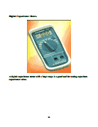
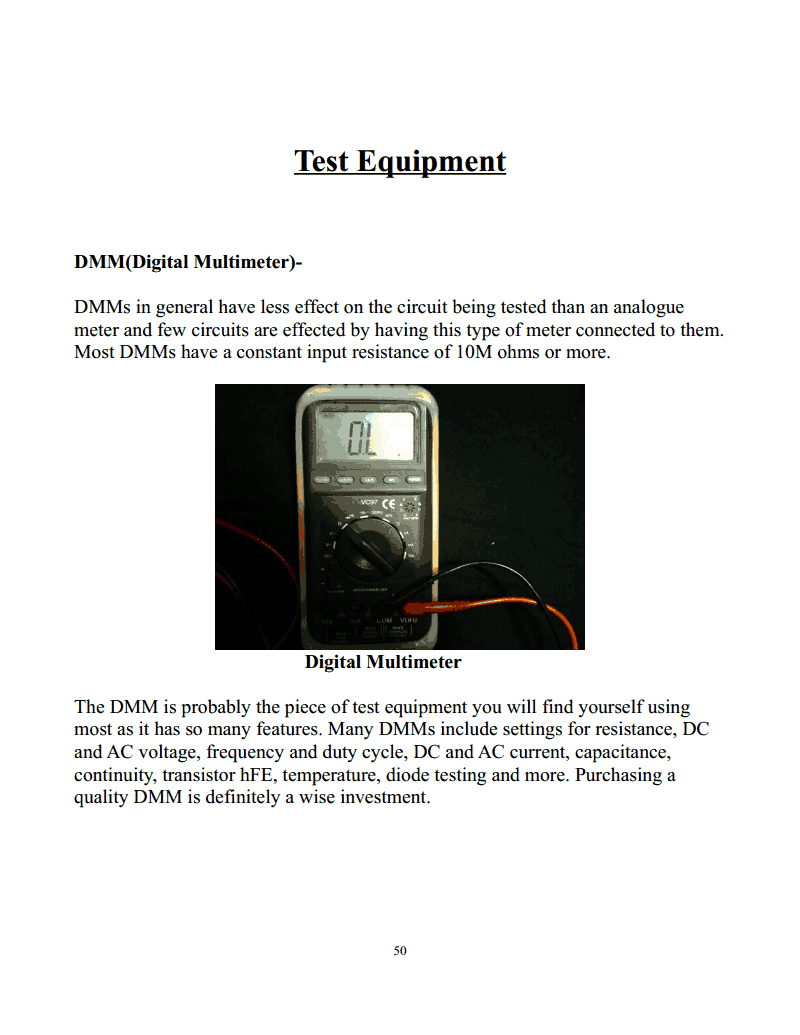
DMM(Digital Multimeter)-
DMMs in general have less effect on the circuit being tested than an analogue
meter and few circuits are effected by having this type of meter connected to them.
Most DMMs have a constant input resistance of 10M ohms or more.
Digital Multimeter
The DMM is probably the piece of test equipment you will find yourself using
most as it has so many features. Many DMMs include settings for resistance, DC
and AC voltage, frequency and duty cycle, DC and AC current, capacitance,
continuity, transistor hFE, temperature, diode testing and more. Purchasing a
quality DMM is definitely a wise investment.
50
Strona 51 z 195.
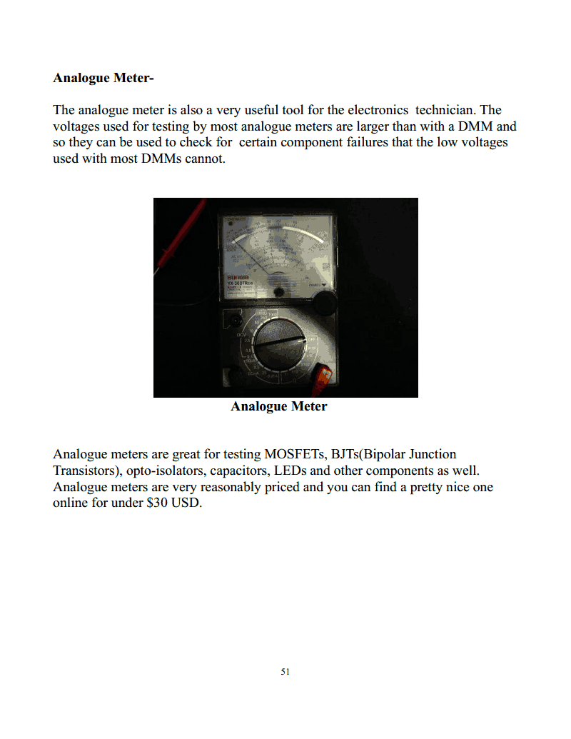
Analogue Meter-
The analogue meter is also a very useful tool for the electronics technician. The
voltages used for testing by most analogue meters are larger than with a DMM and
so they can be used to check for certain component failures that the low voltages
used with most DMMs cannot.
Analogue Meter
Analogue meters are great for testing MOSFETs, BJTs(Bipolar Junction
Transistors), opto-isolators, capacitors, LEDs and other components as well.
Analogue meters are very reasonably priced and you can find a pretty nice one
online for under $30 USD.
51
Strona 52 z 195.
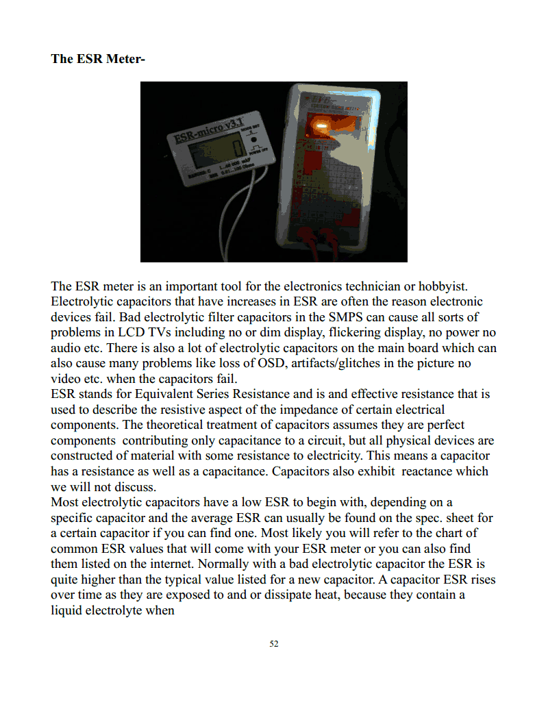
The ESR Meter-
The ESR meter is an important tool for the electronics technician or hobbyist.
Electrolytic capacitors that have increases in ESR are often the reason electronic
devices fail. Bad electrolytic filter capacitors in the SMPS can cause all sorts of
problems in LCD TVs including no or dim display, flickering display, no power no
audio etc. There is also a lot of electrolytic capacitors on the main board which can
also cause many problems like loss of OSD, artifacts/glitches in the picture no
video etc. when the capacitors fail.
ESR stands for Equivalent Series Resistance and is and effective resistance that is
used to describe the resistive aspect of the impedance of certain electrical
components. The theoretical treatment of capacitors assumes they are perfect
components contributing only capacitance to a circuit, but all physical devices are
constructed of material with some resistance to electricity. This means a capacitor
has a resistance as well as a capacitance. Capacitors also exhibit reactance which
we will not discuss.
Most electrolytic capacitors have a low ESR to begin with, depending on a
specific capacitor and the average ESR can usually be found on the spec. sheet for
a certain capacitor if you can find one. Most likely you will refer to the chart of
common ESR values that will come with your ESR meter or you can also find
them listed on the internet. Normally with a bad electrolytic capacitor the ESR is
quite higher than the typical value listed for a new capacitor. A capacitor ESR rises
over time as they are exposed to and or dissipate heat, because they contain a
liquid electrolyte when
52
Strona 53 z 195.
they get hot the liquid expands and is vented out of the capacitor and also the
electrolyte can break down and go through chemical changes over time and
exposure to heat also causing the ESR to increase.
The ESR meter is so valuable because it allows you to quickly check the many
electrolytic capacitors found in LCD TVs and other electronic devices and very
often you can test them in circuit all though if you ever doubt the reading it never
hurts to test the capacitors out of circuit and this is a good practice with all
components or at least to unsolder and lift one of the components leads from the
circuit.
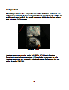
The Ring Tester-
The ring tester is an inexpensive and effective way to test any high Q(quality
factor) inductive component. In LCD TV repair the ring tester is very useful for
testing switching transformers in the SMPS and HV transformers on the inverter
board.
The components in many circuit like the SMPS and inverter board contain low
loss(high Q) resonant circuits. The ring test got its name from the fact that when a
very fast pulse of current is applied to a high Q component the tuned nature of the
component will produce a decaying AC voltage of several cycles or more. The
more rings the higher the Q. Little or no rings indicates low Q and a possible
problem.
53
Strona 54 z 195.
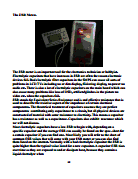
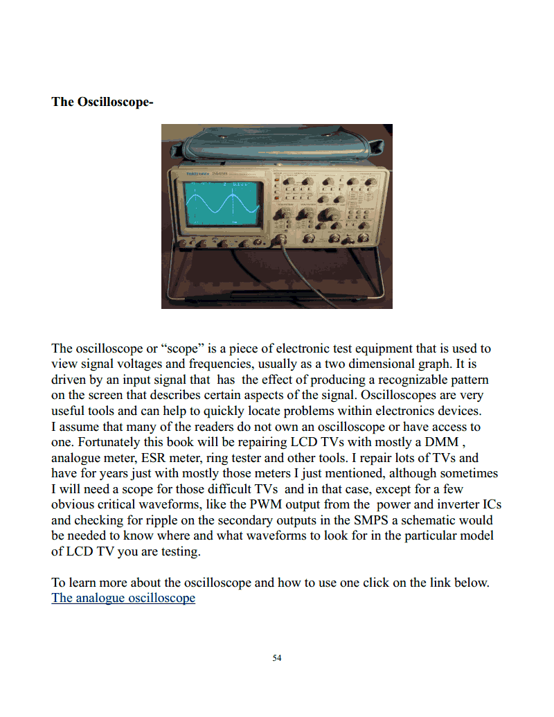
The Oscilloscope-
The oscilloscope or “scope” is a piece of electronic test equipment that is used to
view signal voltages and frequencies, usually as a two dimensional graph. It is
driven by an input signal that has the effect of producing a recognizable pattern
on the screen that describes certain aspects of the signal. Oscilloscopes are very
useful tools and can help to quickly locate problems within electronics devices.
I assume that many of the readers do not own an oscilloscope or have access to
one. Fortunately this book will be repairing LCD TVs with mostly a DMM ,
analogue meter, ESR meter, ring tester and other tools. I repair lots of TVs and
have for years just with mostly those meters I just mentioned, although sometimes
I will need a scope for those difficult TVs and in that case, except for a few
obvious critical waveforms, like the PWM output from the power and inverter ICs
and checking for ripple on the secondary outputs in the SMPS a schematic would
be needed to know where and what waveforms to look for in the particular model
of LCD TV you are testing.
To learn more about the oscilloscope and how to use one click on the link below.
The analogue oscilloscope
54
Strona 55 z 195.
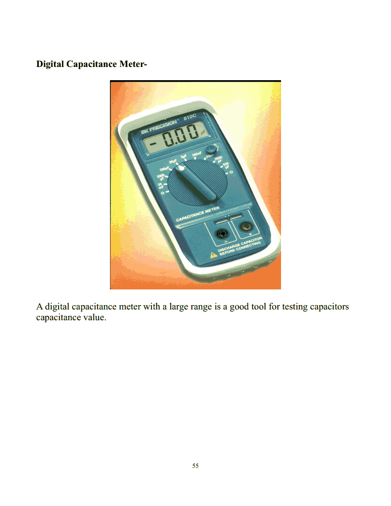
Digital Capacitance Meter-
A digital capacitance meter with a large range is a good tool for testing capacitors
capacitance value.
55
Strona 56 z 195.
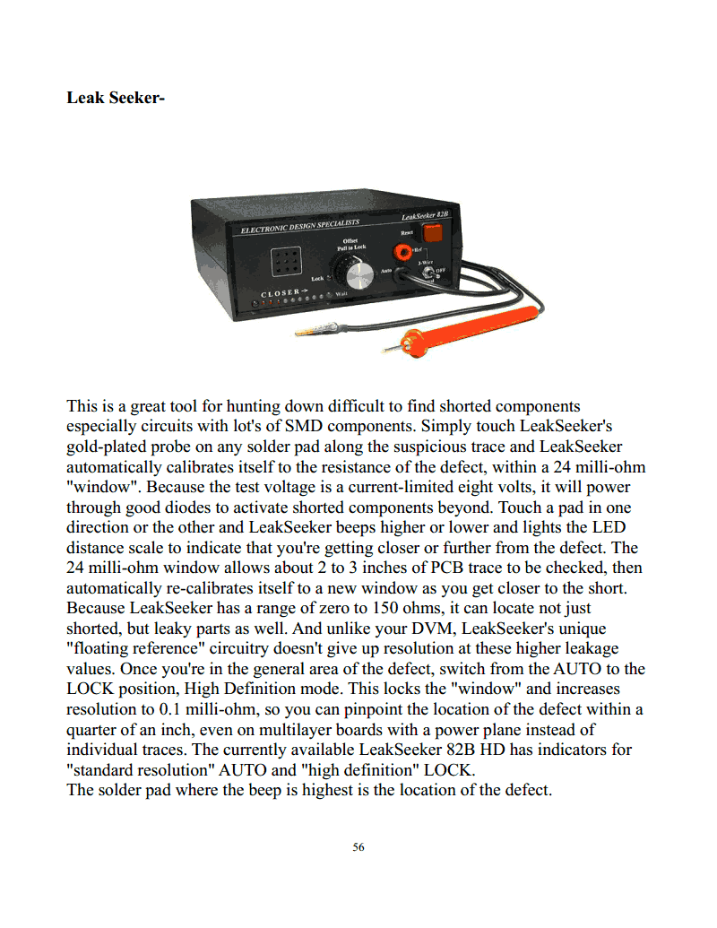
Leak Seeker-
This is a great tool for hunting down difficult to find shorted components
especially circuits with lot's of SMD components. Simply touch LeakSeeker's
gold-plated probe on any solder pad along the suspicious trace and LeakSeeker
automatically calibrates itself to the resistance of the defect, within a 24 milli-ohm
"window". Because the test voltage is a current-limited eight volts, it will power
through good diodes to activate shorted components beyond. Touch a pad in one
direction or the other and LeakSeeker beeps higher or lower and lights the LED
distance scale to indicate that you're getting closer or further from the defect. The
24 milli-ohm window allows about 2 to 3 inches of PCB trace to be checked, then
automatically re-calibrates itself to a new window as you get closer to the short.
Because LeakSeeker has a range of zero to 150 ohms, it can locate not just
shorted, but leaky parts as well. And unlike your DVM, LeakSeeker's unique
"floating reference" circuitry doesn't give up resolution at these higher leakage
values. Once you're in the general area of the defect, switch from the AUTO to the
LOCK position, High Definition mode. This locks the "window" and increases
resolution to 0.1 milli-ohm, so you can pinpoint the location of the defect within a
quarter of an inch, even on multilayer boards with a power plane instead of
individual traces. The currently available LeakSeeker 82B HD has indicators for
"standard resolution" AUTO and "high definition" LOCK.
The solder pad where the beep is highest is the location of the defect.
56
Strona 57 z 195.
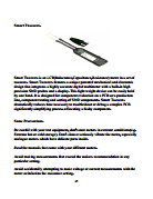
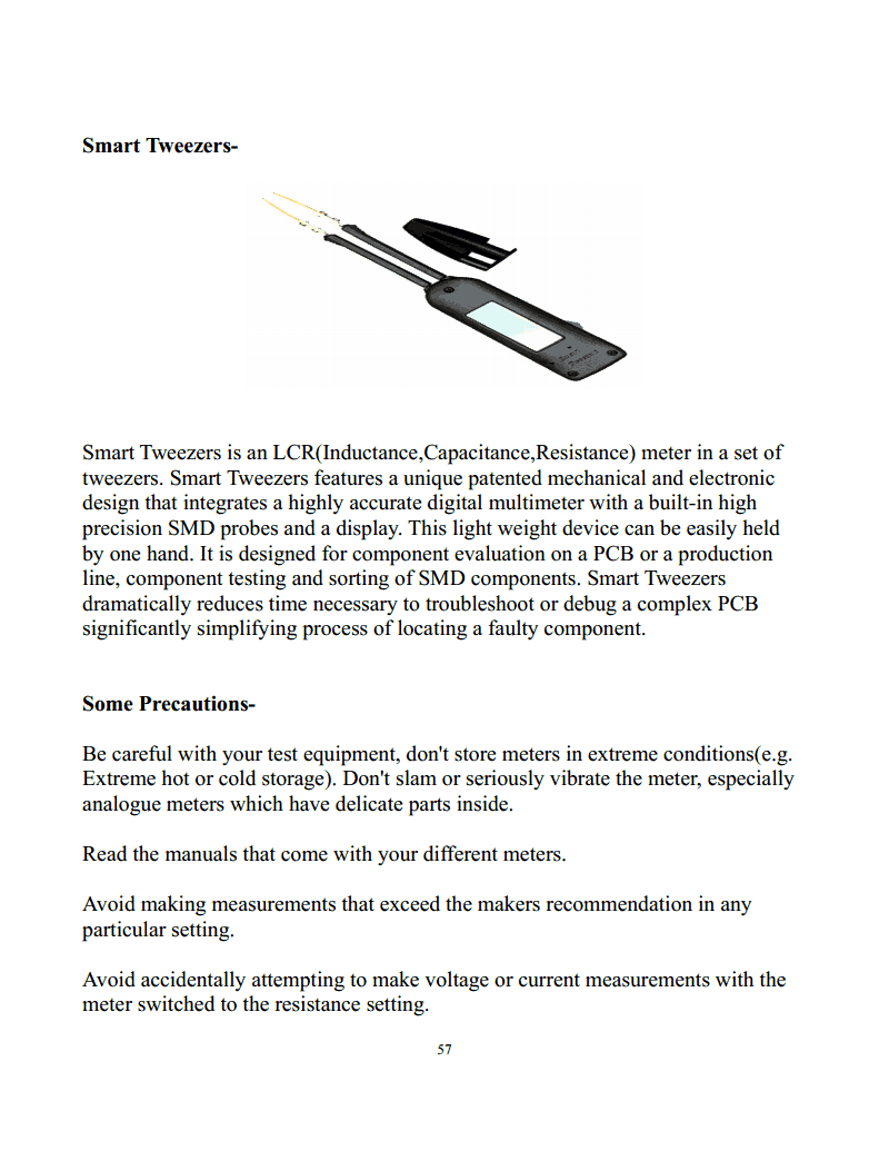
Smart Tweezers-
Smart Tweezers is an LCR(Inductance,Capacitance,Resistance) meter in a set of
tweezers. Smart Tweezers features a unique patented mechanical and electronic
design that integrates a highly accurate digital multimeter with a built-in high
precision SMD probes and a display. This light weight device can be easily held
by one hand. It is designed for component evaluation on a PCB or a production
line, component testing and sorting of SMD components. Smart Tweezers
dramatically reduces time necessary to troubleshoot or debug a complex PCB
significantly simplifying process of locating a faulty component.
Some Precautions-
Be careful with your test equipment, don't store meters in extreme conditions(e.g.
Extreme hot or cold storage). Don't slam or seriously vibrate the meter, especially
analogue meters which have delicate parts inside.
Read the manuals that come with your different meters.
Avoid making measurements that exceed the makers recommendation in any
particular setting.
Avoid accidentally attempting to make voltage or current measurements with the
meter switched to the resistance setting.
57
Strona 58 z 195.
Schematic Diagrams
Schematic diagrams can really make troubleshooting LCD TVs much easier and
can often be found online in service manuals available for download. Many times
though, the service manuals will not have that much info and have only partial or
no schematics at all. This is why it is so important to further your electronics
knowledge and to be constantly studying. The more you know about electronics
and common circuits, the easier it will be for you to recognize the circuits in the
TV you are working on and to quickly see how they work and have a good idea of
where to start troubleshooting the TV regardless of whether or not you have a
schematic diagram. If you have a strong understanding of electronics you will be
able to analyze, troubleshoot and repair any circuit. It still never hurts to see what
information you can find as the internet has made so much available to the
technician and hobbyist repairer that was not available to us in the past so easily.
Here is a link to the best source of great schematics for LCD TVs, much better
than what is found in most service manuals. SAMS Technical Publishing.
58
Strona 59 z 195.
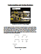
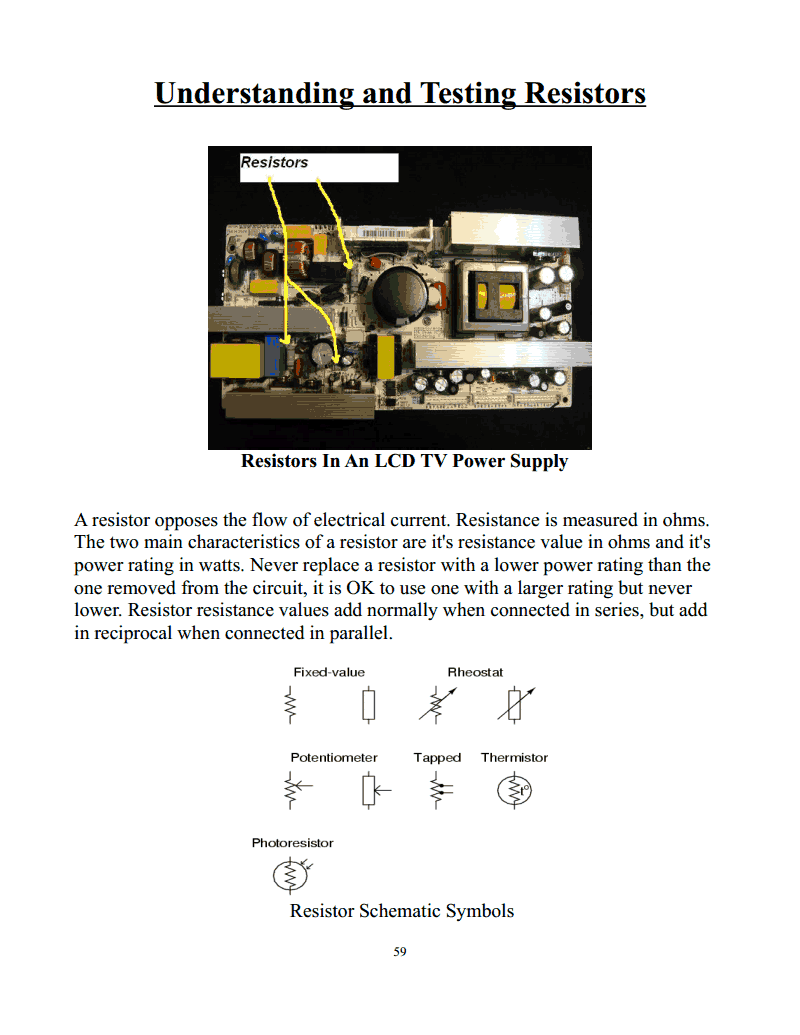
Understanding and Testing Resistors
Resistors In An LCD TV Power Supply
A resistor opposes the flow of electrical current. Resistance is measured in ohms.
The two main characteristics of a resistor are it's resistance value in ohms and it's
power rating in watts. Never replace a resistor with a lower power rating than the
one removed from the circuit, it is OK to use one with a larger rating but never
lower. Resistor resistance values add normally when connected in series, but add
in reciprocal when connected in parallel.
Resistor Schematic Symbols
59
Strona 60 z 195.
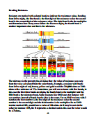
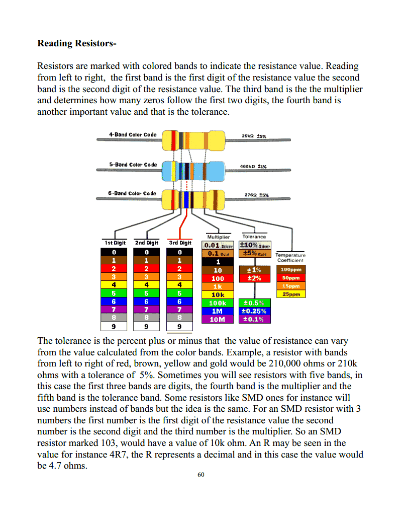
Reading Resistors-
Resistors are marked with colored bands to indicate the resistance value. Reading
from left to right, the first band is the first digit of the resistance value the second
band is the second digit of the resistance value. The third band is the the multiplier
and determines how many zeros follow the first two digits, the fourth band is
another important value and that is the tolerance.
The tolerance is the percent plus or minus that the value of resistance can vary
from the value calculated from the color bands. Example, a resistor with bands
from left to right of red, brown, yellow and gold would be 210,000 ohms or 210k
ohms with a tolerance of 5%. Sometimes you will see resistors with five bands, in
this case the first three bands are digits, the fourth band is the multiplier and the
fifth band is the tolerance band. Some resistors like SMD ones for instance will
use numbers instead of bands but the idea is the same. For an SMD resistor with 3
numbers the first number is the first digit of the resistance value the second
number is the second digit and the third number is the multiplier. So an SMD
resistor marked 103, would have a value of 10k ohm. An R may be seen in the
value for instance 4R7, the R represents a decimal and in this case the value would
be 4.7 ohms.
60
Strona 61 z 195.
Testing Resistors-
Testing resistors can be done with your DMM or analogue meter. Determine the
value the resistor is supposed to be by using the color bands or numeric code. If
the resistor is burnt or discolored so that you can not read the bands you will need
the schematic diagram for the TV you are working on or you will have to use the
techniques described in the book, “Find Burnt Resistor Value” to determine the
resistors value through a systematic process.
61
Strona 62 z 195.
Once you know the value of the resistor you want to test is supposed to be you can
simply set your DMM or analogue meter to the proper resistance range and
measure the actual value of the resistor. You should get a resistance measurement
with in the tolerance of the given resistor, most bad resistors will have increased
in value or gone open reading O.L./ infinite resistance. Charred and burnt resistors
are obviously bad and need replacement. Always remove resistors from circuit
before testing, as surrounding components may cause erroneous readings. Wattage
is not always listed on resistors and is determined by the physical size.
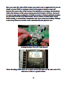
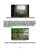
Testing Resistor On LCD Main Board
Meter Reading 218.6 ohms the resistor stated 220 ohms on the side and at 5%
tolerance so this as a good resistor
62
Strona 63 z 195.
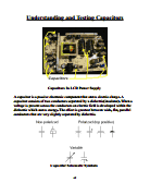
Understanding and Testing Capacitors
Capacitors In LCD Power Supply
A capacitor is a passive electronic component that stores electric charge. A
capacitor consists of two conductors separated by a dielectric(insulator). When a
voltage is present across the conductors an electric field is developed within the
dielectric which stores energy. The effect is greatest between wide, flat, parallel
conductors that are very slightly separated by dielectric.
Capacitor Schematic Symbols
63
Strona 64 z 195.
Capacitors are widely used in electronic circuits for coupling(blocking the flow of
DC while allowing AC to pass), decoupling(also called bypassing, passes DC
while bypassing AC), filtering interference, Smoothing the output from a bridge
rectifier(often called a reservoir capacitor), filtering ripple on the output of SMPS
power supplies, in timing and resonant circuits and many other purposes.
Capacitor capacitance values add normally when connected in parallel, but add in
reciprocal when connected in series. Some important characteristics are the
capacitance value(often in micro-farads) and the working voltage(the max voltage
that can be applied across the capacitor). Never replace a capacitor with a working
voltage lower than the working voltage of the capacitor being replaced. Discharge
capacitors and observe polarity when testing.
Testing Capacitors, method one-
Use your analogue meter set to the x1 ohm range and connect the test leads to the
capacitor. The meters needle should kick up and then return to infinity if it does
not flick or respond reverse the test leads, if it still does not flick try again with
your analogue meter set to x10 ohm, x100 ohm, x1k ohm and then x10k ohm
range until you get a response if the meter needle does not flick when the test leads
are applied to the capacitor in any setting than the capacitor is considered open. If
the needle flicks up and stays at zero ohms the capacitor is considered shorted,
also if it stays to any other value other than infinity after flicking it is leaky. This
method of testing is fairly old and not the best method. Just because a capacitor
can charges does not mean it is a good capacitor. You can also use your DMM set
to the resistance setting to do this test, it should show some reading and then
gradually increase until the value reaches O.L.(Over Limit), and if you reverse the
test leads it should do the same again. This test will not work on small capacitors
10nF or lower.
Method Two-
The second method for testing capacitors is to use a capacitance meter or the
capacitance setting on your DMM, if it has one. By placing the test leads of the
meter to the leads of the capacitor the meter will display the measured value.
The value of measured capacitance should be what is marked on the capacitor(plus
or minus an amount indicated by the tolerance value). Most electrolytic capacitors
in LCD TVs have a tolerance of 20%. Electrolytic capacitors will have the value
of capacitance marked on the side in micro-farads(uF) along with the working
voltage, tolerance and max operating temperature(typically 85 or 105 degrees
Celsius). Most non-electrolytic capacitors will have their value in a numerical
code marked on the side.
64
Strona 65 z 195.
Just like resistors, the first two numbers are the first two digits of the value and the
third is the multiplier. The value will be in pico-farads. These three numbers are
followed by a letter which denotes the tolerance value(the amount that the actual
value of capacitance may very from the value stated on the capacitor). Both
methods one and two are great for testing non-electrolytic capacitors like ceramic
disc, ceramic chip and polyester film type.
Method Three-
This method involves the use of an ESR meter.
ESR Meter
65
Strona 66 z 195.
Electrolytic capacitors are the most common capacitors to fail in electronic devices
and one of the most common components you will find failed in LCD TVs in
general.
Electrolytic capacitors may test fine with methods one and two but can have an
increased ESR which is causing a failure that would be missed by the first two
testing methods. In this case you need the ESR meter to find the bad capacitors. To
use the ESR meter simply place the test leads to the leads of an electrolytic
capacitor and compare the reading(in ohms) to the one on a chart of typical ESR
values for electrolytic capacitors that should come with your ESR meter. Most
ESR meters will have an ESR value chart right on the meter itself.
66
Strona 67 z 195.
You can usually check electrolytic capacitors in circuit (unless testing capacitors in
parallel), but I still recommend pulling them out of circuit or at least de-soldering
and lifting one lead of the capacitor before testing.
Using ESR meter to test SMD electrolytic capacitors on the main board
67
Strona 68 z 195.
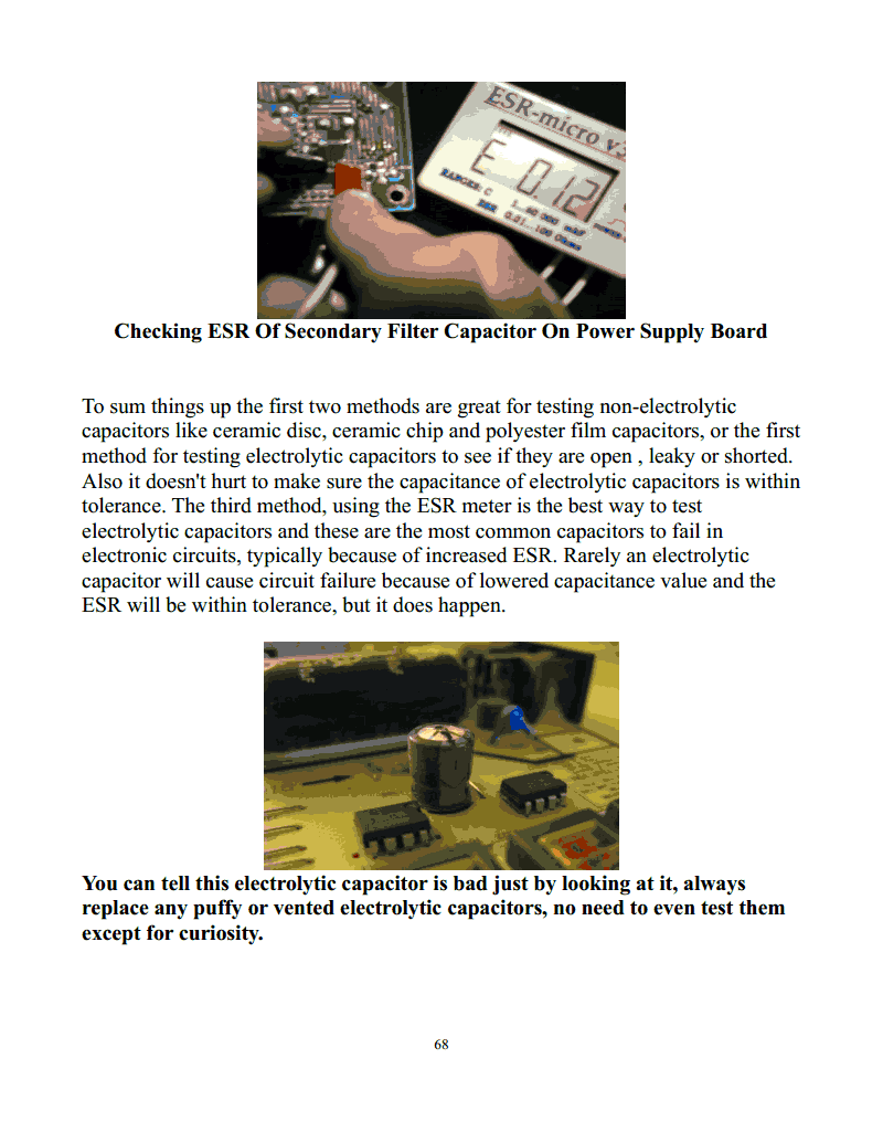
Checking ESR Of Secondary Filter Capacitor On Power Supply Board
To sum things up the first two methods are great for testing non-electrolytic
capacitors like ceramic disc, ceramic chip and polyester film capacitors, or the first
method for testing electrolytic capacitors to see if they are open , leaky or shorted.
Also it doesn't hurt to make sure the capacitance of electrolytic capacitors is within
tolerance. The third method, using the ESR meter is the best way to test
electrolytic capacitors and these are the most common capacitors to fail in
electronic circuits, typically because of increased ESR. Rarely an electrolytic
capacitor will cause circuit failure because of lowered capacitance value and the
ESR will be within tolerance, but it does happen.
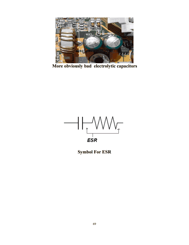
You can tell this electrolytic capacitor is bad just by looking at it, always
replace any puffy or vented electrolytic capacitors, no need to even test them
except for curiosity.
68
Strona 69 z 195.
More obviously bad electrolytic capacitors
Symbol For ESR
69
Strona 70 z 195.
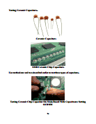
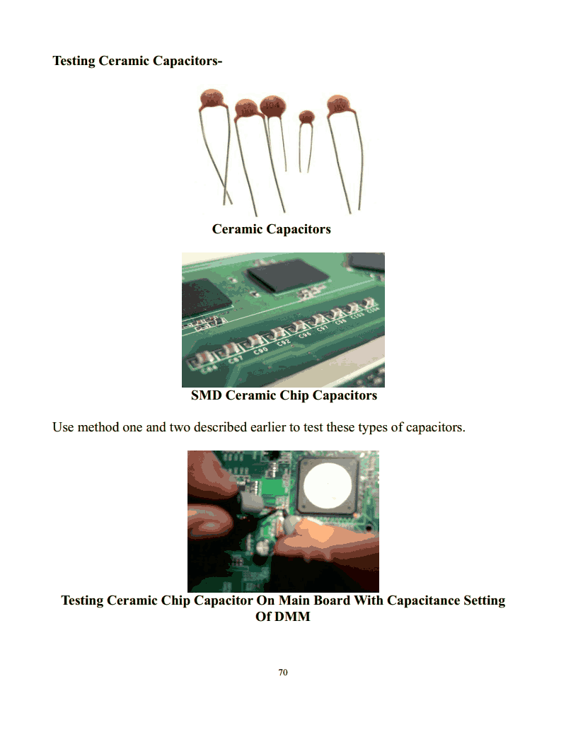
Testing Ceramic Capacitors-
Ceramic Capacitors
SMD Ceramic Chip Capacitors
Use method one and two described earlier to test these types of capacitors.
Testing Ceramic Chip Capacitor On Main Board With Capacitance Setting
Of DMM
70
Strona 71 z 195.
Meter Reading in nF(nanofarads) 0.052 nanofarads or 52 picofarads
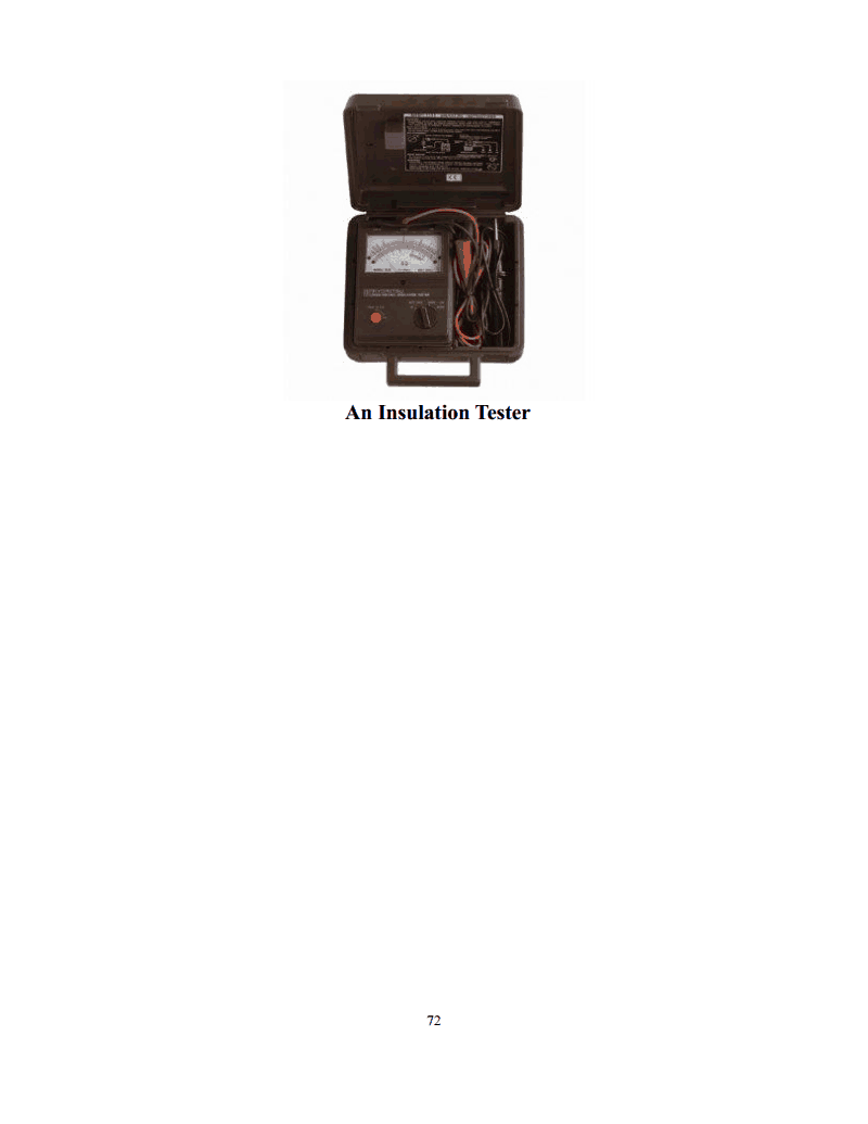
To test the high voltage capacitors like the resin coated ceramic capacitors found
on the secondary side of some inverters, you will have to use an insulation tester
as the low voltage output from your DMM or analogue meter is not enough to test
this type of capacitor for leakage or dielectric breakdown. These capacitors will
often have physical damage that you can see like a crack in the resin coating,
discoloration or burn.
5pF 3KV Ceramic Capacitors on Secondary Side Of An LCD TV Inverter
71
Strona 72 z 195.
An Insulation Tester
72
Strona 73 z 195.
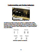
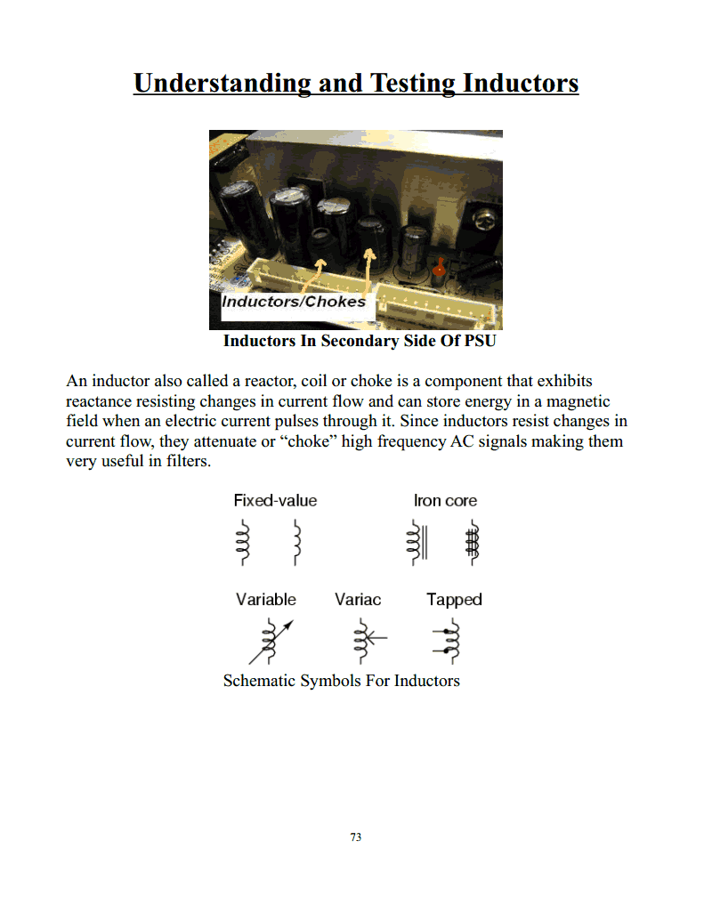
Understanding and Testing Inductors
Inductors In Secondary Side Of PSU
An inductor also called a reactor, coil or choke is a component that exhibits
reactance resisting changes in current flow and can store energy in a magnetic
field when an electric current pulses through it. Since inductors resist changes in
current flow, they attenuate or “choke” high frequency AC signals making them
very useful in filters.
Schematic Symbols For Inductors
73
Strona 74 z 195.
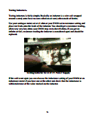
Testing Inductors-
Testing inductors is fairly simple. Basically an inductor is a wire coil wrapped
around a core( some have no core called an air core) often made of ferrite.
Use your analogue meter set at x1 ohm or your DMM set to resistance setting and
place test leads onto the leads of the inductor. You should get a resistance reading,
often very very low ohms your DMM may even show 0 ohms. If you get an
infinite or O.L. resistance reading the inductor is considered open and should be
replaced.
Testing Inductor In LCD TV Power Supply
If the coil is not open you can also use the inductance setting of your DMM or an
inductance meter if you have one or the other and check that the inductance is
within tolerance of the value marked on the inductor.
74
Strona 75 z 195.
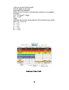
Inductor Color Code
75
Strona 76 z 195.
For high Q(quality factor) low loss coils like the primary winding of the SMPS
switching transformer you should use a ring tester to check for shorts between
turns in the winding.
Place the test leads of the ring tester onto the leads of the inductor and check the
amount of LEDs that light up to indicate the “rings” for the coil you are testing,
the more LEDs the better. Most High Q coils will light up at least one green LED.
You should see what kind of reading you get from various known good inductors,
so you know what kinds of readings you should be looking for when testing
inductors in LCD TVs.
76
Strona 77 z 195.
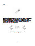
Understanding and Testing Transistors
A transistor is a semiconductor electronic component used to amplify or switch
electronic signals. A transistor is made of doped semiconductor material junctions,
with three terminals for connection to an external circuit. A voltage or current
applied to one pair of the transistor's terminals changes the current flowing
through another pair of terminals(one terminal being common to both pairs).
77
Strona 78 z 195.
BJT-
Bipolar Junction Transistors(BJTs) are made from three sections of semiconductor
material, alternating p type and n type resulting in two pn junctions, one pn
junction existing between the emitter and the base the other existing between the
collector and the base. BJTs are classified as npn or pnp depending on the
arrangement of there n and p type material.
Schematic Symbol
78
Strona 79 z 195.
Testing BJTs-
First determine whether you will be testing an npn or pnp transistor and which
pins are the base, emitter and collector by looking the transistors part number up
online or looking in the LCD TV schematic diagram, if you can not find this
information, use the method found in this book “Testing Electronic Components”
to determine the information stated above.
Once you have determined the type (npn or pnp) of BJT you will be testing and
which leads are the base, emitter and collector you are ready to test. Set your
DMM to the diode test setting. For npn type BJT place the black test lead on the
base pin and the red test lead on the emitter pin and then with the black test lead
still on the base pin put the red test lead on the collector pin, both readings should
be O.L.(Over Limit). Next place the red test lead on the base pin and the black test
lead on the emitter pin and then with the red test lead still on the base pin place the
black test lead to the collector pin. You should get about a 0.4V-0.7V voltage drop
for both readings. Now switch the DMM to the resistance setting, place the black
test lead on the collector pin and the red test lead on the emitter pin, you should
get an O.L. reading and if you reverse the test leads so that the black test lead is on
the emitter pin and the red test lead is on the collector pin, you should again get an
O.L. reading. You can also just leave the meter in the diode test setting when
checking between collector and emitter, you should still get an O.L. reading in
both directions, getting a low voltage drop reading across the emitter and collector
in either direction indicates a short or leakage(note: some BJT have a damper
diode in parallel with the emitter and collector causing a normal 0.4V-0.7V voltage
drop in one direction between emitter and collector). Getting a small voltage drop
reading in both directions between base and emitter indicates a shorted junction,
also if you get a small voltage drop reading in both directions between base and
collector this is also considered a shorted junction. Getting any resistance or
voltage drop(depending on test method) reading between collector and emitter
indicates a short or leakage between collector and emitter. A transistor can have
one or both junctions shorted when they fail and typically will be shorted between
collector and emitter. An O.L. reading in both directions between base and emitter
indicates an open junction as does an O.L. Reading in both directions between
base and collector.
For pnp type BJTs you will perform the same test only it will be done with the
polarity of the test leads reversed for each step.
79
Strona 80 z 195.
Step 1 Testing an NPN BJT With DMM
Step 2 Testing NPN BJT With DMM (Simply Repeat 1 & 2 With Test Leads
In Reverse Polarity For Steps 3 And 4)
80
Strona 81 z 195.
Step 1 Testing an PNP BJT With DMM
Step 2 Testing PNP BJT With DMM (Simply Repeat 1 & 2 With Test Leads
In Reverse Polarity For Steps 3 And 4)
81
Strona 82 z 195.
You can also use your analogue meter to test BJTs. Set your meter to the x1 ohm
range and perform the test in the same manner as with the DMM only instead of a
voltage drop reading you will be looking at a resistance reading(on the lower
portion of many analogue meters indicators you can also read the voltage drop of
the junctions) and the test leads in the resistance setting are reversed in comparison
to a DMM the black test lead is positive and the red test lead is negative, but the
idea is the same between the base pin and emitter pin you should have a low
resistance reading in one direction and an infinite resistance reading in the other
direction readings between the base pin and collector pin will be the same. You
should get infinite reading in both directions between collector and emitter in the
x1 ohm range.
Testing PNP BJT with Analogue meter
Testing PNP BJT with Analogue meter
82
Strona 83 z 195.
Some DMM have a transistor test mode for checking hFE(beta or gain). You can
use this setting to test if a BJTs hFE is within tolerance.
DMM hFE Setting
MOSFETs-
Power MOSFETS IN LCD PSU
83
Strona 84 z 195.
The MOSFET or Metal Oxide Semiconductor Field Effect Transistor is a
component similar to the BJT in the fact that it can amplify or switch electronic
signals. The BJT relies on making a reverse biased junction conduct by applying
an electronic signal to the other junction. The MOSFET or FET(Field Effect
Transistor) is entirely different. In a MOSFET a strip of semiconductor material
either n or p doped between the source and drain is made either more or less
conductive by the presence of an electric charge between the gate and source.
The MOSFET has three terminals or leads, the gate, source and drain. Both n
channel and p channel devices are used in LCD TVs.
Special care must be taken(ESD Bracelet etc.) when handling small signal
MOSFETs, because the gate is completely insulated from the source and drain by
a very thin film of silicon dioxide. The insulation breaks down at roughly 20-100V
depending upon the thickness of the silicon dioxide film.
MOSFET ICs on the inverter board.
84
Strona 85 z 195.
MOSFET Schematic Symbol
Testing MOSFETs-
Once you have looked up the part number of the MOSFET you want to test online
and acquired a data-sheet, found the info in a parts reference manual or looked at
the schematic diagram for the TV you are working on and know the pin
configuration, set your analogue meter to the x10k range to check the MOSFET.
Let's say you are testing an n channel MOSFET, put the black test lead on the
drain pin then touch the gate pin with the red test lead. This will discharge the
MOSFETs internal capacitance. Next place the red test lead to the source pin while
still holding the black test lead to the drain pin. Now take a finger, while still
holding the test leads in place, red on source and black on drain and use that finger
to touch the gate and drain pin at the same time, the analogue meters needle should
move from infinity to around the center position of the meters indicator. Taking the
red test lead off the source pin and placing it back on the source pin the needle
should still go back to the middle of the meters indicator. To discharge the
MOSFET lift the red test lead from the source pin and touch it to the gate pin, this
will discharge the internal capacitance again and if you again place the red test
lead on the source pin and the black test lead to the drain pin, the needle on the
indicator should not move and give an infinite ohms reading. Testing a p channel
MOSFET is the same as for an n channel MOSFET only you will reverse the
polarity of the test leads for each test.
85
Strona 86 z 195.
Step 1 Testing N Channel MOSFET
Step 2 Testing N Channel MOSFET
86
Strona 87 z 195.
Step 3 Testing N Channel MOSFET
87
Strona 88 z 195.
Special testing devices are available just for testing MOSFET transistors.
Alternative MOSFET Test Methods-
DE-MOSFET (Depletion/Enhancement Type,) Test Using an ohmmeter set to
the x 100 ohm scale, measure the resistance between the MOSFET drain and the
source, then reverse the ohmmeter leads and take another reading. The readings
should be equal, regardless of meter lead polarity. Connect the positive lead of the
ohmmeter to the gate. Using the negative lead, measure the resistance between the
gate and the drain and between the gate and the source. Both readings should show
infinity. Disconnect the positive lead from the gate and connect the negative lead
to the gate. Using the positive lead, measure the resistance between the gate and
the drain; then measure it between the gate and the source. Both readings should
show infinity. If the MOSFET has a substrate connection, Disconnect the negative
lead from the gate and connect it to the substrate. Using the positive lead, measure
the resistance between the substrate and the drain and between the substrate and
the source. Both of these readings should indicate infinity. Disconnect the negative
lead from the substrate and connect the positive lead to the substrate. Using the
negative lead, measure the resistance between the substrate and the drain and
between the substrate and the source. Both readings should indicate a low
resistance (about 1,000 ohms).
88
Strona 89 z 195.
E-MOSFET (Enhancement Type, The most common type you will encounter)
Test Using an ohmmeter set to the x 100 ohm scale, measure the resistance
between the drain and the source, then reverse the leads and take another reading
between the drain and the source. Both readings should show infinity, regardless
of meter lead polarity. Connect the positive lead of the ohmmeter to the gate.
Using the negative lead, measure the resistance between the gate and the drain and
then between the gate and the source. Both readings should indicate infinity.
Disconnect the positive lead from the gate and connect the negative lead to the
gate. Using the positive lead, measure the resistance between the gate and the
drain and then between the gate and the source. Both readings should indicate
infinity. If the MOSFET has a substrate connection, Disconnect the negative lead
from the gate and connect it to the substrate. Using the positive lead, measure the
resistance between the substrate and the drain and between the substrate and the
source. Both of these readings should indicate infinity. Disconnect the negative
lead from the substrate and connect the positive lead to the substrate. Using the
negative lead, measure the resistance between the substrate and the drain and
between the substrate and the source. Both readings should indicate a low
resistance (about 1,000 ohms). Most MOSFETs will fail by shorting from drain to
source and sometimes they will also have a short between gate and source or
between gate and drain or both.
You should always try and find a data sheet for the MOSFET you are testing
because you will find some MOSFETs will have different characteristics that will
make the test readings slightly different. For instance the P11NK50Z has a diode
between source and drain, so that when testing you will get a reading in one
direction between source and drain in x100 ohm setting and this is normal.
Always try to use exact replacements when replacing a bad BJT or MOSFET. If
you must use a substitute always replace with the same type(NPN, PNP, N
channel, enhancement mode etc..)BJT and with the same or higher IC(continuous
collector current) and the same or higher VCEO(max voltage as measured between
collector and emitter when base is open that the transistor can handle without
breaking down). Try to match the gain as close as possible. For MOSFETS replace
with the same or higher BVDSS (drain to source breakdown voltage) and the same
or higher ID(continuous drain current). Also if you substitute a transistor used in a
half bridge that uses two identical transistors replace both the transistors in the half
bridge so that both of the transistors are the same, don't just replace the bad one in
this case.
89
Strona 90 z 195.
Understanding and Testing Diodes
Diodes In LCD TV Standby Circuit
A diode is an electronic component that allows electric current to flow in only one
direction. The word diode is usually associated with the semiconductor diode
which is the most common diode in use at the time I am writing this. The
semiconductor diode is made up of a pn junction.
Rectifier Diode Shown Next To Schematic Symbol
90
Strona 91 z 195.
Schematic Symbols For Different Types Of Diodes
91
Strona 92 z 195.
Testing The Diode-
Using your DMM set to the diode test mode, place the black test lead on the
cathode(marked with a band) lead of the diode and the red test lead on the anode.
You should get a voltage drop reading of between 0.45V-0.7V. Reverse the test
leads so that the red test lead is on the cathode and the black test lead is on the
anode and you should get an O.L. Reading.
If you get a low reading in both directions the diode is considered shorted and if
you get an O.L. reading in both forward and reverse bias directions the diode is
considered open, in both cases the diode must be replaced. Most commonly diodes
will be shorted.
When replacing diodes try to use exact replacements. If an exact replacement is
not possible you can use a substitute with the same or higher PIV(peak inverse
voltage), this is the max amount of instantaneous reverse bias voltage that the
diode can withstand without breaking down(avalanche effect) listed on data sheets
as VRRM (maximum repetitive reverse voltage) and the same or higher average
forward current, this is the maximum amount of current the diode can withstand
when forward biased listed on data sheets as IF(AV).
92
Strona 93 z 195.
Step 1 Testing Diode With DMM
Step 2 Testing Diode With DMM
Testing Diodes With analogue Meter-
Using your analogue meter set to the x1 ohm range place the red test lead on the
cathode and the black test lead on the anode, you should get a low resistance
reading and reversing the test leads you should get a reading of infinity. On the
lower portion of the indicator of many analogue meters there is also a scale for
reading the diode junction voltage drop.
93
Strona 94 z 195.
Now set the meter to x10k ohm range and repeat the same test, you should get the
same results. When you have the red probe on the anode and the black probe on
the cathode in the x10k ohm range getting any reading means the diode is leaky
and must be replaced.
Step 1 Testing Diode With Analogue Meter Set To x1 ohm Range
Step 2 Testing Diode With Analogue Meter Set To x1 ohm Range
94
Strona 95 z 195.
Step 1 Testing Diode With Analogue Meter Set To x10k ohm Range
Step 2 Testing Diode With Analogue Meter Set To x10k ohm Range
95
Strona 96 z 195.
Schottky Diodes-
Schottky Diodes In LCD TV SMPS
Schottky diodes also known as hot carrier diodes are semiconductor diodes with a
lower forward voltage drop than a standard diode and a very fast switching action.
When a current flows through a diode there is a voltage drop which as stated
earlier is about 0.45V-0.7V for normal diodes, but a schottky diodes voltage drop
is between 0.15V and 0.45V, the lower voltage drop means higher circuit
efficiency. The most important feature of the schottky compared with the normal
pn diode is reverse recovery time, the time it take to switch from conducting to
nonconducting and nonconducting to conducting. Schottky diodes can look very
similar to normal diodes in design. Often they come in a dual package with the
two diodes cathodes being common.
Dual Package Schottky
96
Strona 97 z 195.
Testing Schottky Diodes-
Once you know the diode you are going to test is a schottky than you need to use
your analogue meter and set it to the x10k ohm range. Testing is similar to the
normal diode only you will get a reading in both directions. This is a normal
characteristic of a schottky diode. The reading should be almost full scale
deflection(low resistance)with the red test lead on the cathode and the black test
lead on the anode, then with the black test lead on the cathode and the red test lead
on the anode you will get a small leakage reading (large resistance). If you get two
almost full scale deflection readings(low resistance) the schottky diode is shorted
and needs to be replaced, if the resistance reading is infinite in both directions the
schottky diode is open and must be replaced. Testing the schottky in the x1 ohm
range will be just like testing a normal diode, also note that not all schottky diodes
will give a reading in both directions when set to x10k but just be aware that this
kind of diode when normal can have a reading in both directions when measuring
in the x10k setting unlike a normal diode.
Step 1 Testing Schottky Diode In x1 ohm Setting
97
Strona 98 z 195.
Step 2 Testing Schottky Diode In x1 ohm Setting
Step 3 Testing Schottky Diode In x1 ohm Setting
98
Strona 99 z 195.
Step 4 Testing Schottky Diode In x1 ohm Setting
You can also test schottky diodes with the diode test mode of your DMM just like
we did with the standard diode earlier. Expect lower junction voltage drops when
testing schottky diodes with the diode test mode of your DMM compared to those
of the standard diode.
Always find an exact replacement for the schottky and ultra fast recovery diodes
used for rectifying the secondary voltages in the PSU. When substitution is
necessary you must follow the voltage and current replacement guidelines
discussed earlier for standard diodes but also you must make sure the replacement
has the same or faster trr(maximum reverse recovery time), this only applies to
ultra fast recovery diodes as schottky diodes data sheets won't list trr but a schottky
diode is a high speed diode so always use a schottky diode to replace another
schottky diode.
Zener Diodes-
Zener Diodes In LCD TV SMPS Secondary side
99
Strona 100 z 195.
A zener diode is a diode that not only permits current flow in the forward bias
direction but also in the reverse bias direction when the voltage applied is greater
than the breakdown voltage called the zener voltage(also called the avalanche
voltage). A zener diode exhibits very similar properties to that of a normal diode
except it is specially designed to have a low reverse breakdown voltage or zener
voltage. This is done by heavily doping the pn junction of the diode. Doping is the
process of introducing specific amounts of impurities to the semiconductor
material for the purpose of changing it's conductivity. The breakdown voltage of
zener diodes can be controlled quite accurately through the process of doping.
Common breakdown voltages range from around 1.2V to 200V. Zener diodes are
normally used as a voltage reference or as shunt regulators for voltage regulation
in smaller circuits because of their ability to maintain a fairly constant voltage
drop with a varying current.
Testing Zener Diodes-
Testing zener diodes is best done with a zener diode tester.
100
Strona 102 z 195.
Connect the zener diode you want to test in series with a resistor to limit current
flow through the testing circuit(the value of the resistor will depend on the zener
diode and how much current it is rated for). Then connect the ammeter of proper
size or the current setting of your DMM set to the proper range in series with the
zener diode and resistor. Connect the cathode end of the diode to the positive
terminal of the variable DC power supply and the free anode to the negative
terminal of the DC power supply. Turn on the variable DC power supply and
slowly increase the voltage. No current should flow through the circuit as
indicated by the ammeter until the voltage is raised to the breakdown(actually a
reverse or avalanche breakdown) voltage of the zener diode under test.
Example Zener Diode Test Circuit
When replacing zener diodes always try to use an exact replacement but when
necessary use a substitute with the exact same VZ(zener voltage) and the same or
higher IZM(maximum zener current).
102
Strona 103 z 195.
Understanding and Testing Bridge Rectifiers
Bridge Rectifier In LCD TV PSU
The purpose of the bridge rectifier is to convert AC voltage into DC voltage.
Symbol For Bridge Rectifier
A bridge rectifier is an arrangement of four diodes in a bridge configuration and
commonly comes in one integrated package containing all four diodes. A diode
bridge or a bridge rectifier give full wave rectification.
103
Strona 104 z 195.
Bridge Rectifier IC
104
Strona 105 z 195.
Testing Bridge Rectifiers-
Using your analogue meter set to x10k ohms range place the test leads to the
negative and the first AC pin and then reverse the test leads, you should show a
low resistance in one direction and infinite reading in the other direction. Next do
the same test with the negative pin and the second AC pin the results should be the
same. Now do the same tests only with the positive pin and both the AC pins, the
results should again be the same. If you find low resistance readings in both
directions on any of these tests then the bridge rectifier must be replaced as one or
more of the internal diodes is shorted, also if you get an infinite reading in both
directions the bridge rectifier must be replaced as one or more of the diodes is
open. If instead of a bridge rectifier in integrated package you find four individual
diodes in a bridge configuration, test each diode individually and if even one diode
is faulty replace all four.
Step 1 Testing Bridge Rectifier IC
105
Strona 106 z 195.
Step 2 Testing Bridge Rectifier IC
Step 3 Testing Bridge Rectifier IC
106
Strona 107 z 195.
Step 4 Testing Bridge Rectifier IC
Step 5 Testing Bridge Rectifier IC
107
Strona 108 z 195.
Step 6 Testing Bridge Rectifier IC
Step 7 Testing Bridge Rectifier IC
108
Strona 109 z 195.
Step 8 Testing Bridge Rectifier IC
The bridge rectifier can also be tested with the diode test mode of the DMM of
course. Do the test in the same way testing each of the four diodes that are inside
the bridge rectifier IC only instead of resistance you will be looking at the diode
junction voltage drops.
Use exact replacements for bridge rectifiers when possible but if necessary to use a
substitute then find one with the same or higher VRRM (maximum repetitive
reverse voltage), the same or higher IF(AV)(average forward current) and the same
or higher VRMS(maximum RMS(root mean square) bridge input voltage).
109
Strona 110 z 195.
Understanding and Testing LEDs
LEDs On LCD TV Status Board
An LED or Light Emitting Diode is a semiconductor component source of light.
LEDs are used as indicator lights in LCD TVs. The LED is based on the
technology of the semiconductor diode, when an LED is forward biased (turned
on) electrons recombine with holes inside the component creating an effect called
electroluminescence.
110
Strona 111 z 195.
Up close Picture of SMD LEDs
Schematic Symbol In Comparison With Physical LED
111
Strona 112 z 195.
Testing LEDs-
Testing an LED is very simple, it will emit light when forward biased and will not
emit light when reverse biased. If an LED does not light when forward biased then
it has gone open circuit and must be replaced. To test, set your analogue meter to
x1 ohm range. Place the red test lead on the cathode pin this side is indicated by a
flat spot on the plastic package or a line on SMD packages, the anode side will not
have the flat spot. While the red test lead is on the cathode touch the black probe
to the anode pin and the LED should light, remove lead quickly after LED lights
so as not to damage it.
Testing SMD LED On LCD TV LED/Status Board
If you reverse the test leads the diode will not light. If the diode does not light in
either direction and also gives a low resistance reading in both directions than the
diode is considered shorted. You can also check LEDs with the diode test setting
of your DMM. You should get a voltage drop of around 1.75V in the forward bias
direction and O.L. in reverse bias direction. A reading of O.L. in both directions
means the LED is open and a low voltage drop in both directions(typically 0.00V)
means the LED is shorted.
112
Strona 113 z 195.
Understanding and Testing Switching
Transformers
Switching Transformer In LCD TV PSU
Basic Transformer Schematic Symbol
113
Strona 114 z 195.
Switching transformers also called SMPS or power transformers are found in the
SMPS of LCD TVs. A switching transformer does not actually switch anything
itself it is merely a transformer that is designed specifically for use in a switching
power converter or SMPS and designed for the high frequency switching(10s to
100s of kilohertz) in SMPS type power supplies. They are smaller and lighter than
the typical transformer found in a linear power supply and also use a ferrite core
instead of laminated iron. The function of the switching transformer is to convert a
voltage applied across it's primary winding into a lower or higher voltage across
it's secondary windings depending on the amount of turns in the primary and
secondary windings of the switching transformer(the turns ratio). Switching
transformers are robust components and rarely breakdown, and when they do it
will normally cause components in the primary side of the switching transformers
circuits that drive it's primary winding to blow/fail as well and most likely open
the main fuse. The most common failure is a shorted primary winding. The
switching transformer secondary windings seldom have issues in the LCD TV
SMPS due to the fact that voltage is stepped down so the secondary windings have
very few turns and a low voltage across them. The primary winding however has
many turns and a larger voltage across it. To test the primary winding of the
switching transformer use a ring tester. Locate the primary winding
114
Strona 115 z 195.
Place the test leads of the ring tester to the two pins of the primary winding. Most
switching transformers will light up four to eight LEDs, of course if you can,
check your reading against that of known good switching transformer that is the
same exactly as the suspected one under test. Often this is not possible, so if you
only light up one to two or no LEDs it is most likely that the switching transformer
primary has shorted windings and needs to be replaced. If the switching
transformer tests bad always remove it from the circuit board and test again to be
sure. If it tests good out of circuit suspect other failed components in the SMPS
perhaps a shorted secondary side schottky or ultra fast recovery diode. If a
switching transformer is found to be bad you may have trouble finding an exact
replacement and you may have to find a company or person online that will
rewind it for you or you can attempt to rewind it yourself with instructions found
online, but be warned this is not an easy task. You can also check switching
transformers for an open primary winding although it is not a common failure. Set
your DMM to the ohms setting or your analogue meter to x1 ohm range. Check for
a low ohms reading across the primary winding. If the reading is O.L. or infinity
than the winding is considered open and the transformer must be replaced or
rewound. You can also check the secondary windings to make sure they are not
open the same way you check the primary and if you have another of the same
switching transformer to compare with you can ring the secondary windings as
well although because they have less windings they will not light up as many
LEDs, even only one LED or none and this is normal. If you get no rings on the
secondary windings you can also check them with an ESR meter and compare
with another of the same transformer, because the windings have a certain
inductive reactance at the ESR meters test frequency(typically 100kHz) and a
resistance that together make up a complex impedance, the windings will give a
reading on the ESR meter, typically a high reading like 45 ohms or beyond the
range of the meter. If you read zero ohms on the ESR meter this would be a sign
of shorted secondary windings. You can also measure the resistance(many
secondary windings will read 0 ohms using the resistance setting of your meter use
your ESR meter to measure the impedance in this case) or inductance values of the
secondary windings and compare the results to a good transformer that is the same
as the one in question. Another test is to set your analogue meter to the x10k ohms
range and place one test lead on a pin of the primary side and the other lead touch
to the pins on the secondary side. You should get an infinite or O.L. reading
between the primary and secondary windings.
115
Strona 116 z 195.
Checking For Open Primary Winding In SMPS Switching Transformer
116
Strona 117 z 195.
Understanding and Testing Opto-Isolators
Opto-isolators In LCD TV SMPS
An opto-isolator also called an opto-coupler or photo-coupler is a component that
allows a signal to pass from one circuit to another but allows the two circuits to
remain electrically isolated. The most common opto-isolator which comes in IC
package consists of an LED which shines onto the base of a photo-transistor
(usually an npn transistor) and allows current to flow from collector to emitter
until the LED is turned off. When a signal is applied to the LED it then shines light
that is varied in brightness with the same amplitude as the input signal, this light
lands upon the photo-transistor (the resistance of the collector/emitter junction
now changes with the varying light) which passes the signal onto the next circuit.
117
Strona 118 z 195.
Testing Opto-Isolators-
Using your analogue meter set to the x1 ohm range test the LED side of the opto-
isolator. Which will be found be looking up the part number online or referring to
the LCD TVs schematic. A common opto-isolator found in LCD TVs is the 817
type for instance the PC817.
118
Strona 119 z 195.
Multiple Package Types
Placing the test leads on both pins of the LED side of the opto-isolator and then
reversing them you should get a low resistance reading in one direction and
infinite reading in the other. If you get a low resistance reading in both directions
the LED side is shorted and the opto-isolator needs to be replaced. If you get an
infinite reading in both directions, the LED side is open and again the opto-isolator
must be replaced.
Next you must test the transistor side of the opto-isolator. Some opto-isolators will
have six pins in which case the three pins that correspond to the transistor side of
the IC will be base, emitter and collector and on the LED side the three pins will
be the anode, cathode and one pin with no connection. If you have a six pin opto-
isolator, testing will be the same as for a four pin, just remember to check the pin
configuration. If you have a four pin opto-isolator which I find is most common in
LCD TVs, then set your analogue meter to the x10k ohm range and place the test
leads on the two pins of the transistor side which will be the emitter and collector
and then reverse the test leads. You should get a high resistance (typically around
500k ohms) reading with the test leads in one direction and an infinite reading in
the other direction.
119
Strona 120 z 195.
Six Pin Opto-isolator
If you get a high resistance reading or low resistance reading in both directions the
opto-isolator must be replaced. Now set the meter to x1 ohm range and place the
test leads on the emitter and collector in both directions again, now you should get
only an infinite reading in both directions, otherwise the opto-isolator must be
replaced.
120
Strona 121 z 195.
Step 1 testing LED side
Step 2 testing LED side
121
Strona 123 z 195.
Understanding and Testing Voltage Regulators
Voltage Regulator ICs on LCD TV Main Board
A voltage regulator is an electronic circuit designed to automatically maintain a
constant output voltage regardless of fluctuations in input voltage or current draw
from the load(to an extent).
123
Strona 124 z 195.
Testing Voltage Regulator IC-
To test the voltage regulator IC you must check it in circuit with the TV plugged in
and the LCD TV turned on. Power the TV on and set your DMM or analogue
meter to the proper DC voltage setting. Place your black test lead to cold ground
and carefully place your red test lead to the output pin of the regulator, usually pin
three on many voltage regulators, like the LM7805. Remember to always look up
your part numbers for the part you are testing if needed so you can be sure to test it
properly.
Typical LM7805 Package
Now you should expect the output voltage to be within tolerance of the regulators
specified voltage. So for an LM7805 you should expect about 5.1V-5.9V DC, if
you measure a low voltage like say 1V you should turn the TV off and unplug it
then lift the output pin of the regulator from the circuit. Then power the TV on
again and retest checking the voltage right on the lifted pin, If the voltage is back
to around 5V again instead of 1V then the IC is most likely good and you should
suspect shorted components in the circuit after the regulator that are pulling down
the voltage. If the voltage is still low then the regulator is most likely bad and
needs to be replaced(granted the input voltage is good). If you measure OV or low
voltage on the output you should check the voltage on the input of the voltage
regulator and make sure it is at least the expected regulation voltage plus the
regulators “drop out” voltage. The drop out voltage is the voltage that the input
must be above the regulation voltage for the given regulator, to maintain a
regulated output. For instance if a LM7805 had a drop out voltage of 2V then it
would require at least a 7V input to maintain a 5V regulated output. If the input
voltage is low suspect bad components in the circuit supplying input voltage to
the regulator.
124
Strona 125 z 195.
Checking Input Voltage to Regulator
Checking Output Voltage From Regulator
125
Strona 126 z 195.
Understanding and Testing Switches
Typical Tactile Switch Found In LCD TVs
A switch is an electronic component which can break a circuit or divert current
from one part of a circuit to another part. The most common type of switch you
will see in LCD TVs is the tactile switch or “tact switch”. The common
configuration is single pole single throw, normally open or “push to make”
momentary contact.
Switch Schematic Symbols
Testing Tactile Switches-
126
Strona 127 z 195.
Testing tactile switches and any switch in general is very simple. Set your DMM
to the resistance or continuity setting or your analogue meter to the x1 ohm range
and place the test leads on to pins on opposite sides of the switch(polarity does not
matter). You should get a reading of infinity. Now while still keeping the test leads
on the pins, depress the button and the meter indicator should give a low resistance
reading and when you release the button the indicator should return to O.L. or
infinity. Please note this is only for testing single pole single throw, normally open
or “push to make” momentary contact switches, but I think you can see how easy
it would be to test any switch with the resistance setting of your meter.
127
Strona 128 z 195.
Understanding and Testing Fuses and Varistors
Fuse In LCD PSU
Pico/Nano Fuses On LCD TV Inverter Board
128
Strona 129 z 195.
A fuse is an electronic component that is used as a sacrificial device for over
current protection. It contains a wire or strip that melts when too much current
flows though it, which interrupts the circuit that it is connected to. A fuse is
destroyed by excessive current so that further damage or injury is prevented from
overheating or fire. Always replace a fuse with the exact same value, type and
rating as the one removed from the circuit.
Schematic Symbol For Fuse
Testing Fuses-
Set your DMM to the resistance or continuity setting or your analogue meter to x1
ohm range. Place the test leads the terminal caps or leads of the fuse(polarity does
not matter), you should get a very, very low resistance reading of zero or very
close to zero ohms. This is the characteristic of a good fuse. A bad fuse will give a
high, O.L. or infinite resistance reading. You can visually inspect glass fuses and
see when they have blown(blackened glass), or the metal strip has just slightly
opened but if a fuse looks good you must still test it because you can see when a
fuse is bad but you cannot see that it is good, meaning just because it looks good
does not mean that it will not test bad.
Testing A Fuse
129
Strona 130 z 195.
Testing A Pico/Nano Fuse
Varistors
The name Varistor is a portmanteau(blend of two or more words) of variable resistor(this is misleading
as varistors are quite different from a variable resistor). Varistors have non-ohmic current-voltage
characteristics, at low currents and voltages a varistor exhibits a high resistance but at higher voltages
and currents the resistance drops dramatically. Varistors are often used to protect circuits against
transient voltages by placing them into a circuit in such a way that when triggered, they will shunt the
current created by the high voltage away from the rest of the circuit preventing damage. In an LCD TV
power supply you will find them right after the main fuse connected across the hot and neutral. The
most common type of varistor is the metal oxide varistor or MOV. A shorted varistor will cause the
main fuse to open.
Testing Varistors-
1.inspect varistor for obvious external damage(burns and cracks etc..)
2.Set multimeter to resistance setting and measure the resistance of the varistor by placing the red test
lead to one terminal of the varistor and the black to the other terminal(polarity does not matter).
3.Reverse multimeter test leads.
4.Resistance readings should be infinite ohms or O.L.(over limit) in both directions.
130
Strona 131 z 195.
Some Testing Tips
-Always test components with a meter that is known to be good, with fresh
batteries installed.
-I suggest removing components from the circuit before testing. Often surrounding
components in the circuit cause erroneous readings to occur. At least lift/remove
one lead from the circuit for most components.
-Learn how to test all electronic components and practice testing them so you can
feel confident in yourself when testing components. Again I highly recommend the
book “Testing Electronic Components” , as I was not able to completely go over
all the components found in electronic circuits and how to test them.
-Learn how to use your test equipment. Read the manuals and understand all the
functions and settings. Your test equipment is your best friend when repairing
LCD TVs. The better you know how to use your test equipment the faster and
easier it will be to apply them to testing circuits and you may even develop some
new testing methods yourself.
131
Strona 132 z 195.
Useful Formulas
These are just examples of the basic and most commonly used formulas in
electronics. You should know These by heart. There are many more that you
should study and learn as well if you plan to further your understanding of
electronics. These formulas are to be used for DC circuits or resonant AC(Meaning
voltage and current are in phase and that the circuit Impedance is equal to the
circuit resistance) circuit calculations.
132
Strona 133 z 195.
How To Disassemble An LCD TV
First start by laying a thick soft blanket out on a table large enough to lay the face
of the LCD TV on.
Lay The LCD TV On Its Face
Next remove all the screws from the stand and remove the stand. Next remove all
the screws from the back of the TV, it help to have a cup to keep all the screws in.
133
Strona 134 z 195.
Remove the back and set it aside. Now you will have full access to the
PCBs(Printed Circuit Board). To remove a PCB for component testing or for
replacement, simply disconnect any cables going to the board from their
connectors. Label them if necessary.
Exposed PCBs
134
Strona 135 z 195.
Next remove all the screws that hold the PCB to the TV. The board should now
come loose. You may now test or replace components on the board you
removed(remember if you remove the PSU the first thing you need to do is to
discharge the reservoir or primary side filter capacitor).
135
Strona 136 z 195.
Voltage Test Points
Warning!!!
Be careful when taking voltage measurements. Remember when taking
measurements on the primary/hot side of the SMPS use the corresponding primary
side ground(hot ground) and when taking measurements on the secondary/cold
side use the secondary(cold ground).
Bridge Rectifier-
136
Strona 137 z 195.
Plug the LCD TV in and locate the AC pins of the bridge rectifier marked by a
wavy line(this is the AC symbol). Set your DMM or analogue meter to the proper
AC voltage setting. Now place your test leads against the AC pins of the bridge
rectifier. Hold them tightly and carefully in position be sure not to slip and short
anything with your test leads.
Placing Test Leads on AC Pins Of Bridge Rectifier
You should get a reading of around 110-120 volts AC(USA, in some other
countries the voltage may be different find out the mains in your country and this
is what you should expect) If you get zero volts then check in the circuits before
the bridge rectifier, could be bad components in the EMI circuit like an open
common mode choke, open thermistor, blown main fuse, bad AC cord, electrical
receptacle has no power, bad components in passive PFC circuit if the TV uses this
type of PFC, bad solder connection in circuits before or at bridge rectifier etc.
137
Strona 138 z 195.
Reservoir Capacitor/Primary Filter Capacitor-
Once we have confirmed that the bridge rectifier is receiving an AC input at the
proper voltage we can now expect to find a DC voltage at the pins of the
reservoir/primary filter capacitor. Make sure the TV is plugged in. Now set your
DMM or analogue meter to the proper DC voltage setting place your black test
lead to the negative pin of the reservoir capacitor, next place the red test lead on
the positive pin of the reservoir capacitor. Be extremely careful not to accidentally
slip and short the pins of the capacitor together.
Testing Voltage At The Reservoir/Primary Filter Capacitor
You should get a reading of around 150-160V DC(USA, If active PFC is used
expect around 350-400V).
If you get the right reading then move on to the next voltage test. If you get zero or
very low voltage check the corresponding circuit components, look for bad solder
connections, cracks in the copper traces, check the components in the active PFC
circuit(MOSFET, diode, PFC controller IC) remove and test the bridge rectifier
etc.
138
Strona 139 z 195.
Power IC-
First you must look up the part number of the power IC you will be testing the
positive supply voltage pin of. Once you locate the positive supply voltage pin of
your power IC, set your DMM or analogue meter to the proper DC voltage range.
Place the red test lead to the positive voltage supply(Vcc) pin and the black test
lead to hot ground(reservoir capacitor negative pin). Remember the TV needs to
be plugged in. You should get a reading that corresponds to the proper voltage for
the power IC normally between 16-20V DC. If you get the correct reading you can
assume all components up to this point must be good(bridge rectifier, fuse, EMI
Filter circuitry, start up circuit, etc.). If you can't find the necessary information for
you IC you can always skip to the next voltage test. If the reading is low or zero
volts the most common reason is that the start up circuit resistor/s have changed
value or opened. To find the start up circuit resistor/s, trace back from the positive
voltage supply pin to the large value resistor/s that bring the
SMD Type Power IC/Half Bridge Driver
139
Strona 140 z 195.
Power IC And MOSFET In A Single Package
Testing Positive Supply Voltage Pin Of Power IC
voltage from the positive pin of reservoir capacitor to the Vcc pin of the power IC
so that it can get power before the SMPS is on. Once the TV is on a secondary
winding on the SMPS switching transformer in the primary side of the PSU
supplies voltage to the power IC, this winding and a few other components like a
resistor, a diode that rectifies the output from the secondary winding and a filter
capacitor make up the “run DC” circuit. Some start up circuits will grab voltage
directly from the AC line and not the reservoir capacitors positive pin in which
case you will also find a rectifier diode and filter capacitor in the start up circuit
that should also be checked.
140
Strona 141 z 195.
Testing Secondary Output Voltages-
This is a very simple test for sure. Place your red test lead from you DMM or
analogue meter on the cathode side of the secondary output diode you want to
check and place your black test lead cold ground. Make sure your meter is set to
the proper DC voltage setting( most LCD TVs have secondary voltages of 5V,
12V and 24V but their can be more or different ones, if possible refer to the
service manual of the TV you are testing). Turn power on to TV. You should
receive a DC voltage that corresponds to the voltage you expect at that diode. You
may have to look at a schematic. If you get a good reading on all secondary
diodes, then you can assume that all the components on the primary side are
working properly and checking components in the primary side of the SMPS
would just waste your time most
Checking Secondary Voltage
likely. It obvious if the bridge rectifier, power IC, power MOSFET and etc. were
bad we would not get any of our secondary voltages. You can also check
secondary voltages on the output cable connectors of the PSU which are often
labeled.
141
Strona 142 z 195.
Main Board Voltages-
If all of your voltage were good in the previous test next you should check that
voltage is coming to the main board. If it is low or not present you know it must be
something between the main board and the SMPS after the secondary diode,
perhaps a bad filter capacitor, shorted components or maybe even a bad ribbon
cable or bad solder connections etc. If the voltage is present to the main board then
you can next check the voltage at the output of the voltage regulators that will be
found on the main board typically 5V and 3.3V(and others, it depends on the TV)
linear regulators. If the outputs are correct you can them move on to test the
Positive supply voltage at each of the ICs on the main board. You may need a
schematic or service manual which can usually be found online, to get the pin
layout and Vcc voltage for each IC.
Checking For Voltage To Main Board
142
Strona 143 z 195.
Checking Vcc Voltage OF LVDS IC
(Note this board is removed from the TV, but obviously when doing voltage tests
boards must be in the TV and completely connected properly)
Checking Positive Supply Voltage Pin Of A NAND Memory IC
(Please use a very fine test lead when checking Vcc/Vdd of SMD ICs as the pins are very close
together)
T-con Board Voltage-
With your DMM set to the proper voltage setting, place your black test lead to
cold ground and you red test lead to the the lead of the pico/nano fuse closest to
the cable that brings the voltage to the board, then check with the red test lead to
the pico/nano fuses other lead(terminal caps if SMD). You should get about 12V
DC for both reading. If you only get one reading(on the side closest to the
connector) The fuse has most likely gone open, try replacing it. If you get no
reading on either lead, trace back and check all the components in the circuit that
supplies the voltage to the T-con board.
143
Strona 144 z 195.
The Tap Test
This is an old test that is crude and simple, but it does work. Use this test to isolate
connection problems or intermittent failures caused by bad solder connections etc.
Using the back of your screwdriver or some slightly heavy non conductive tool,
lightly tap around on the circuits careful to not damage any components or bend
leads and cause shorts. The idea is to find the most sensitive part of the circuit that
responds to your tapping causing the TV to go in and out of failure. When you find
this sensitive area or maybe the only area where you get a reaction, inspect all the
components for any damage and then look over all the solder connections
carefully with a magnifier and light or a lit opti-visor. Look for cold solder joints,
ring cracks or any solder joints that are questionable. Mark every bad or
questionable solder connection you see with a marker. After you are done marking
every solder connection go back with your soldering iron and some quality solder
and re-solder all the marked connections.
144
Strona 145 z 195.
Ring Crack
Cold Solder Joints And Some Ring Cracks
You may also find that the connections are all good, but when you tap right on a
component the TV fails. You should directly replace the component if possible.
145
Strona 146 z 195.
Freeze Spray and Hair Dryers
This is another test which will help you isolate a problem to a single area of the
LCD TV. You may run into TVs that will not run properly until sometime after the
TV has been turned on and warmed up. You may also come across LCD TVs that
runs fine until some time after being turned on and then after warming up has a
failure, maybe shutting down, distorted video, distorted audio etc. In the case that
you have a TV that has a failure from start up which goes away after warming up
you can try the hair dryer method. Let the TV set set for awhile so it is cool. Then
turn the TV on and verify it is having the known failure. Then take the hair dryer
and heat up the circuits with a smooth even action and carefully and slowly
panning across them until you find a location that gives you a reaction. If you heat
that area the TV starts to function properly. Once you have isolated the problem to
any area recheck(by starting the test from cold again) to make sure, once verified
check all the components in the isolated area.
146
Strona 147 z 195.
If you can not find any bad components or connections you may want to directly
replace components in this area if you have the parts. Now if you have a TV that
falls into the other category. Working fine at start up and then failing after
warming up then you will use the freeze spray. Turn
Using Hair Dryer
on the TV and let it warm up and stop operating normally, once this happens
power off and unplug the TV use the freeze spay to cool down a section of one of
the PCBs and components in the TV carefully going over all that section(but do it
quick), after thoroughly cooling quickly plug in and turn on the set and see if
failure is gone, meaning that an area you cooled down caused the TV to start
functioning properly again if not, try again with another section, remember you
have to be quick enough to make sure the TV circuits in general don't all cool
down causing the TV to work normally as well. You need to make sure it is when
you spay the freeze spay on that area that the TV is made to start working meaning
you have isolated the problem. The most efficient way is to use freeze spray that is
safe for use on live circuits so that you can spray components while the TV is
running and look for normal operation after a component or area has been sprayed.
The small nozzle of the cool spray allows you to more precisely cool a small
location unlike the hair dryer that's more wide spread when it heats, this will allow
you to isolate the problem to a smaller area of a circuit and maybe even a single
component. Once the problem is isolated carry on as you did previously in the hair
dryer example.
147
Strona 148 z 195.
Using Cool Spray
(Note the board is removed from the TV in this photo but this is actually done as
described earlier with the boards in the TV and completely connected)
148
Strona 149 z 195.
Connection Problems
Solder Cracks
Loose Cables
Connection problems, we discussed some of them earlier in the book, can cause a
lot of problems and you will find they are the reason for a good number of failed
TVs. Most commonly you will find ring cracks and cold solder connection and
even totally burnt up connections when inspecting PCBs with a magnifier or an
opti-visor. Sometimes you will also find cables that have slightly crept out of their
corresponding connectors causing a connection problem.
149
Strona 150 z 195.
Connection problems will often cause intermittent issues but not always when they
are really bad effectively causing a part to be removed from circuit or causing an
open circuit in which case they will cause constant issues. Connection problems
are so common in LCD TVs the first thing you may want to do is open the TV,
inspect all solder connections on each PCB and re solder all questionable ones and
bad ones. Re-seat all the cables into their corresponding connectors, careful not to
bend or break any pins on the cable connector.
Inspecting PCB For Bad Solder Connections
Re seating Cable To Its Connector 1
150
Strona 151 z 195.
Re seating Cable To Its Connector 2
Re seating Cable To Its Connector 3
Once finished double check and make sure everything is properly reassembled and
turn the TV on to see if the problem still persists.
151
Strona 152 z 195.
PSU (Power Supply Unit) Failures
152
Strona 153 z 195.
Now we will go over some common LCD TV PSU failures. PSU failure is quite
common in LCD TVs, so I suggest you study as much as you can about SMPS and
SMPS troubleshooting, as these are the types of PSUs used in LCD TVs. We can't
cover everything in this book but we will cover the most common failures.
-TV is dead(no power and standby LED not lit) and main fuse is blown.
Check for shorted bridge rectifier, shorted diodes in primary side(especially
snubber diodes), reservoir capacitor(check for short and leakage), varistor(check
for visible damage and low resistance reading)and check for shorted power
MOSFETS. If you find lot's of shorted components in the primary side, replace the
power IC along with replacing all the bad components as it will often have been
destroyed as well.
153
Strona 154 z 195.
-No power, standby LED not lit and Main fuse is not blown.
Check the standby power circuit check the voltage at the secondary output
diode(typically 5V DC) cathode if not present or within tolerance check
corresponding components. Check the secondary diode, filter capacitor and choke
of the standby circuit. I have repaired dead LCD TVs with a shorted standby
circuit secondary diode and LCD TVs that would not power on and the standby
LED would flicker caused by bad secondary output filter capacitors in the standby
circuit causing the failure. Note that a blinking LED can indicate a failure code
from the MCU, and the failure may not even be related to the power supply. If you
get a pulsing LED that seems rhythmic or in a pattern( like 3 flashes pause two
flashes repeat, etc.) refer to the service manual to see if the TV has LED blink
codes or not and if so what they are as they can lead you to the right circuit for
repair.
-TV has no power, Power/standby LED is lit and fuse is not blown.
Check for Vcc voltage to the power IC. If not present check start up resistors in the
start up circuit.
-Start up circuit
The start up circuit usually consists of one or more large value resistors that drop
the voltage from the 150-160V source at the positive pin of the reservoir capacitor
to a voltage that is used to power the power IC when the SMPS is not on. The start
up circuit may also grab voltage from the AC line in which case it will typically
also have a rectifier diode and a filter capacitor that should be checked.
154
Strona 155 z 195.
Some more common failures.
-One or more secondary outputs with voltage out of tolerance or with ripple at
mains frequency(50/60 Hz) or twice the mains frequency(100/120 Hz). Check the
reservoir or main filter capacitor for high ESR. Also check surrounding
components in the primary side.
-One or multiple secondary outputs with voltage out of tolerance and or ripple at
the SMPS switching frequency(usually 10s to 100s of kHz). Check the secondary
filter capacitors and chokes. Also if secondary voltage is low, check for shorted
components in the circuit that could be dragging down the voltage.
-Whining noise coming from PSU with low voltage on one or more secondary
outputs. Check for shorted semiconductors( diodes, BJT etc.) in the corresponding
circuit.
-TV power supply making cycling/pulsing or chirping sound. This is almost
always caused by shorted/failed components in the secondary side of the SMPS.
Check secondary output diodes, secondary output filter capacitors, also check the
feedback circuitry, meaning check the opto-isolators,directly replace the adjustable
shunt regulator, check the resistors in the sampling circuitry etc.
155
Strona 156 z 195.
A bad power IC can also sometimes cause the power cycling symptom. If you
have tried and checked everything with no success, you might try directly
replacing the power IC.
-Intermittent power failures. This can be a frustrating thing to troubleshoot. You
will want to use the tap method discussed earlier in the book because most
intermittent failures in general are caused by loose/dry, burnt or oxidized solder
connections. If checking and re soldering all the connections does not work the
next think I would do is check all the electrolytic capacitors in the PSU as they can
also cause intermittent failures.
-Replacing a PSU over repairing it. Sometimes you will have a PSU board with
such extensive damage, say from a power surge that you will really need to
consider looking up the price for a new PCB online as it may not be worth your
time to try and save one that needs so much work done, but if you are like me you
are going to try to fix it anyways to gain skills and satisfaction in a repair.
156
Strona 157 z 195.
Please note:
PSU board connection problems and especially filter capacitors with raised ESR
are so common and cause so many different problems in LCD TVs that may not
even appear to be PSU related that the first thing I do on all repairs is inspect the
PSU and check every electrolytic capacitor on the board, If all is good I then do
the same on the rest of the PCBs.
157
Strona 158 z 195.
Inverter Board Failures
Most inverter board failures will cause one of these two symptoms. Either the
TV will turn on but as soon as the back light turns on the TV shuts down(this
can be very quick, the TV may just quickly flash and you must watch closely)
or the TV will turn on and operate normally with audio but no picture. If you
look carefully you can see that the picture is their but it has no back light to
illuminate it. If you have one of these symptoms you will want to start by
checking the inverter board(after checking the electrolytic capacitors in the
PSU, they can also cause these same symptoms even a dim flickering display
as well when the secondary filter capacitors on the voltage supply line to the
inverter board go bad).
158
Strona 159 z 195.
You may also have TVs with dim display or flickering display which is
usually the inverter board also. Please note that these symptoms can also be
caused by a bad CCFL
-Checking the inverter board
Check the pico/nano fuse/s usually found close to the cable connector that
connects the cable coming from the PSU to the inverter board.
-If the pico/nano fuse or fuses are open, you might first try replacing them
and see if this fixes the problem(normally it won't), if it does not move on to
checking the components in the inverter circuits(if only one of multiple
pico/nano fuses is open check components in the circuit that correspond to
that fuse). Inverter ICs are robust and don't fail very often. Suspect shorted
MOSFET Ics(very common), HVTs(High Voltage Transformers) shorted
between primary and secondary windings, shorted secondary or primary
windings in HVTs, compare results with known good HV transformer of
same type. Fortunately there are usually more than one on LCD TV inverter
boards so you can compare them against each other as most likely not all are
bad(remember to pull them off the board to test and to identify the primary
and secondary pins, they may not be the pins you assumed). Check that the
resin coated ceramic capacitors on secondary side of inverter circuit are not
shorted or leaky.
159
Strona 160 z 195.
LCD TV HVT
-If no pico/nano fuses are open on the inverter board, check the HVTs, check
for open secondary windings(common failure) and shorted turns in both the
secondary and primary windings with ring tester. You can also check for
shorted secondary windings by checking the resistance of the HV
transformers secondary windings and comparing them to each other. A
secondary winding that has shorted turns will have a resistance that is
significantly lower than the rest of the secondary windings. Remember that
bad secondary filter capacitors in the PSU output that supplies voltage to the
inverter board can cause symptoms that are the same as a failed inverter
board. Also check the components in the feed back/Over Load/Open lamp
Protection circuit of the inverter board. When the inverter board shuts down
you should also first check to see if the voltage to the inverter board coming
from the PSU is still present and within tolerance as the problem may be with
the power supply and not the inverter.
Click on the link below to see a repair I did on a TV with a shorted high voltage
transformer(HVT):
http://preher-tech.com/Documents/LCD%20TV%20with%20a%20bad%20HVT.pdf
160
Strona 161 z 195.
Inverter Board Feedback and Over Load Protection Circuit
If you can not find anything wrong with the inverter board or PSU it is likely
you have one or more bad CCFL. You can use a CCFL tester for LCD TVs to
find and then replace the bad CCFLs or you can directly replace all the
CCFLs which wouldn't hurt since even ones that are not bad will likely be
right behind the bad ones. Check the CCFLs for physical damage like
blackened ends and for bad connections.
LCD TV CCFL tester
161
Strona 162 z 195.
Using an LCD TV CCFL tester
Always check for loose or dry solder joints on the HVTs, MOSFET ICs and
inverter IC pins. These are a very common cause of inverter failure.
Sometimes you will not be able to find any good info for the parts on an
inverter board or parts may not be available in which case you may want to
just look into replacing the whole inverter board, usually they are not to
expensive especially compared to replacing the TV. Also always save old
inverter boards and all LCD TV boards for that matter so you can salvage
parts from them that you may not have been able to acquire any other way.
162
Strona 163 z 195.
Main Board Failures
Common main board failures can include no video, no OSD(On Screen
Display/Menu), no audio, tuning problems, video and audio distortions, no color,
white screen etc. Main board failures can also cause no power and in this case will
most likely have a symptom like blinking power/standby LED(often a code
indicating the section/PCB of the TV that is failing), amber colored standby LED
or some color other than normal standby or power etc and LED not lit. The PSU
must get a start up or “on” signal from the MCU on the main board in order for
the TV to turn on and in some designs the inverter also gets an “on” signal from
the main board as well. If you are suspecting main board problem, first check for
proper voltages to main board and ICs, you might need to get a schematic or
service manual or study the board and look up the ICs online to get an idea of what
the voltages you are looking for are, but typically you will have voltages like 5V,
3.3V, 1.8V, 12V and 2.8V DC. Check the outputs from the voltage regulator ICs
and make sure they are within tolerance. Remember to use cold ground when
checking voltages on the main board. If all voltages are present and within
tolerance remove the main board and inspect for bad solder connections and then
check all the electrolytic capacitors like the SMD decoupling capacitors and also
check the ceramic chip or disc bypass capacitors. Pay special attention to the
electrolytic filter capacitors in the voltage regulation section of the main board.
163
Strona 164 z 195.
Check components surrounding ICs including crystals and SMD capacitors.
164
Strona 165 z 195.
SMD Ceramic Chip Capacitors
SMD Electrolytic Capacitor
Crystal-
A crystal oscillator is an electronic circuit that uses the mechanical resonance of a
vibrating crystal of piezoelectric material to create an electrical signal with a very
precise frequency. This frequency is commonly used to keep track of time (as in
quartz wristwatches), to provide a stable clock signal for digital integrated circuits,
and to stabilize frequencies for radio transmitters and receivers. The most common
type of piezoelectric resonator used is the quartz crystal, so oscillator circuits
designed around them were called "crystal oscillators".
165
Strona 166 z 195.
Quartz crystals are produced for frequencies from a few tens of kilohertz to tens of
megahertz. Over two billion crystals are manufactured annually. Most are small
devices for devices such as wristwatches, clocks, radios, computers, and
cellphones. Quartz crystals are also found inside test and measurement
equipment, such as counters, signal generators, and oscilloscopes.
Testing Crystals can be simple. Set your DMM to the frequency setting(if it has
one, if not you can use a frequency counter) and place the red test lead on one of
the crystals pins(TV Must be powered on)and black test lead to cold ground, The
frequency should be within tolerance of the frequency labeled on the crystal. You
will not be able to test all crystals as some will be out of the range of your meter.
Also take into account your meters accuracy. If you have a scope you can also use
it to test crystals again if it's range is withing the frequency of the crystal you want
to test.
Testing SMD crystal with frequency setting of DMM
If you get no frequency reading this could indicate a bad crystal, SMD capacitor in
the oscillator circuitry or a bad IC, check the surrounding components in other
words SMD capacitors etc.. Try directly replacing the crystal. If the surrounding
components test good and/or replacing the crystal does not work most likely the
corresponding IC is bad, in this case the main board will most likely have to be
replaced as replacement ICs can be hard to find and even if you could get them
many are in BGA(Ball Grid Array) or other SMD package which require special
equipment and or skill to replace.
166
Strona 167 z 195.
Testing SMD capacitor on main board
Firmware upgrades-
Sometimes main board type failures can be solved by uploading the flash
memories firmware, or reprogramming a corrupted flash with the original
firmware. Firmware can normally be downloaded and put on a flash drive or
memory stick to be put in the USB port or memory card reader of the LCD TV by
visiting the manufacturers website or calling them and ordering it.
167
Strona 168 z 195.
Sometimes you may need to purchase the firmware and in this case the company
usually sends a thumb drive with the firmware on it.
Flash/Thumb Drive
168
Strona 169 z 195.
No Video
If you have a TV that works fine but has no video(blue screen, white screen etc.),
first check the obvious and make sure it is not a problem with the video
source(DVD player cable box etc.) or a connection problem like a loose cable
between the video source and the TV. After verifying that the source and
connections to the TV are good we can move on. No video can be caused by an
inverter board failure, but this is not common in LCD TVs, as usually the feedback
circuitry for the TV will shut the TV down in the event of inverter board failure.
Look closely at the TV if it is black but you can kind of see video when looking
closely than this verifies that it most likely is the inverter board, but remember it
could always be bad electrolytic capacitors on the PSU board. If you can tell that
the back lights are lit and you have OSD(On Screen Display) but no video than
you most likely have a tuning issue(like a failed digital tuner) with the main board
or maybe something simple like your on the wrong input or a setting in menu for
instance like needing to switch from antenna to cable. It could also be a bad VPU
or other another IC on the main board, check all the main board and main board IC
voltages and make sure they are within tolerance.. If you are using the co-axial
connection on the tuner you may also have a bad tuner, verify by fist running
through a different tuning source for instance a cable box or VCR first, then to the
TV if this fixes the problem you know the tuner is bad and needs to be replaced. If
you have checked the obvious like the menu setting then you should follow the
procedure for checking the main board. Try a firmware upgrade, sometimes no
video can also be caused by a bad controller board(not when OSD is visible).
Check to see if the pico/nano fuse on the controller board is open or has a high
resistance value if so try to replace it(unlike most fuses, pico/nano fuses have a
tenancy to sometimes open for no reason) if replacing open fuse only causes fuse
to blow again you can try fixing the controller board by tracing down shorted
components with a tool like the leak seeker or checking for shorted components
with your multimeter. In most cases you will need to replace the controller board.
Don't forget to look for solder connection problems on the main board or jack pack
when troubleshooting video and audio problems, especially right on the
connectors that the video/audio source cables plug into. Often cracks develop in
the solder connection because of cables being pushed in and pulled out of the
video/cable cable connectors.
169
Strona 170 z 195.
Checking controller board pico/nano fuse
If the pico/nano fuse is good and you have scope verify output signal from main
board, if present and testing main board checked good check all components
possible on controller board or directly replace, if controller board is found to be
good, then the most likely case is the main board will need to be replaced if you
can not find the bad components on the main board . Remember to check all the
electrolytic capacitors on the main board, main board and IC voltages and IC
surrounding components.
Electrolytic capacitors on LCD TV main board
170
Strona 171 z 195.
No Audio
As usual check the obvious, like the connections from the audio source to the TV
and check in the user settings within the menu to make sure the speakers are not
turned off. Sometimes issues such as low audio while watching DTV but normal
Audio during analogue programming etc. can be fixed with a firmware upgrade.
Remember bad filter capacitors on the PSU as well as the main board can cause all
kinds of problems like no audio or intermittent audio. Check the Vcc at the audio
processor and the audio amplifier ICs, if no or low voltage is present lift the Vcc
pin from circuit, if the voltage returns after removing the ICs pin suspect the IC is
bad and replace, if voltage stays low or is not present after lifting pin suspect
components in the voltage supply line to the IC.(remember to always check
surrounding corresponding circuit components). Again don't forget to look for
solder connection problems on the main board and or jack pack for video and
audio problems, especially right on the connectors that the video/audio source
cables plug into. Often cracks develop on the solder connections because of cables
being repeatedly pushed in and pulled out of the video/cable connectors or because
the cables get tugged on, tripped over or moved around to often.
171
Strona 172 z 195.
OSD/Menu Failure
If you have no on screen display or no menu or erratic menu functions, you may
also have menu functions but the user setting can not be saved, or reset every time
the TV power is cycled. This indicates an MCU or VPU failure and or EEPROM
failure and in most cases unless you have another main board to swap ICs from,
and in the case of the VPU very specialized expensive equipment for testing
removal and replacement, you will have to replace the main board. Remember to
check all components surrounding the MCU and VPU like SMD capacitors,
resistors, crystals etc. and also always check all the electrolytic capacitors on the
main board.
172
Strona 173 z 195.
White Screen
If the LCD TV powers on with an all white screen(can also be all black screen
with back lights lit depending on panel design), first as usual inspect the PSU for
bad solder connection and check all the electrolytic capacitors on the PSU. Next
check the pico/nano fuse on the controller/T-con board. Remember the controller
board is ESD sensitive, so take the proper precautions when testing the board.
Check the LVDS cable from the main board to the controller board and make sure
it is not loose. Also check the solder connections on the cable connectors. Make
sure voltage is present at the t-con board.
Cable from main board to controller board
173
Strona 174 z 195.
Check and re seat the FPC or the flat flexible cable from the controller board to the
driver board.
Flat flexible cable connecting controller board to driver board
If all the previous checks out good then check the main board components like
electrolytic capacitors etc.
If the pico/nano fuse on the controller board is open you can try replacing the fuse
to see if it will fix the TV, If the fuse opens again you can replace the controller
board or use a tool like the leak seeker to find the shorted components on the
controller board or use your meter to check for shorted compoents. Usually with
controller boards it is best to just replace the PCB. Most of the time white display
is caused by a bad controller board or bad electrolytic capacitors in the
PSU(secondary filter capacitors on the voltage line to the controller board) or in
the voltage regulation section of the mainboard.
174
Strona 175 z 195.
Rainbow Screen
Steps for troubleshooting the rainbow screen or colored lines screen. First check
the LVDS cable from main board to controller board is not loose. I check that the
cable itself is actually good and re seat the LVDS cable, replace LVDS cable if
necessary. Re seat FPC from the controller board to the driver board and also
check the solder connections on the cable connectors to the boards. Check solder
connections and components on the controller PCB. If everything checks good,
although this still could be a main board issue it is most likely a bad controller
board IC or the panel. More likely the LCD panel has a bad driver board/driver
ICs, but use the procedure for checking the main board before you spend the
money to replace a panel if you actually decide to or if the cost is economical.
Note that you can almost never find the LCD panel alone, but only a full display
panel which has the back light assembly and all. Most people refer to this whole
assembly as the LCD panel, but actually you can disassemble and remove the
actual LCD panel like the photo on page 35. Together the LCD panel, and the back
lights make the LCD display. Usually when you order a full display(listed as panel
with part distributors) it will also have the controller PCB mounted to the back
already but not always so ask, this can be good if you are not quite sure if the LCD
panel or controller PCB are causing the issue.
175
Strona 176 z 195.
Screen Flashes Then TV Shuts Down
If you turn on the LCD TV and it flashes, meaning that the back light comes on for
just a moment and then the TV shuts down this almost always indicates an inverter
board failure. Go over the methods for testing the inverter board. Remember check
the electrolytic capacitors in the PSU, especially the secondary side filter
capacitors that are filtering the ripple from the PSU voltage output that goes to
inverter board.
176
Strona 177 z 195.
No Back light
This is when the LCD TV turns on and works normally has audio and if you look
closely it has OSD, video etc., but the display is not illuminated. This is almost
always an inverter board failure. Go over the procedure for troubleshooting the
inverter board. As I have said many times now check the electrolytic capacitors in
the PSU, especially the secondary side filter capacitors that are filtering the ripple
from the voltage output that goes to the inverter board.
177
Strona 178 z 195.
Lines In Picture
Vertical and horizontal lines as well on the display are almost always caused by
bad connections from the driver board to the panel. In this case the display or
panel must be replaced unless you have the specialized equipment necessary or
can come up with a device to safely redo all the connections on the FPC that
connects the driver board to the panel and even if you could repair the connection
there is still a chance you could have a bad driver IC on the FPC.
FPC(Flexible Printed Circuit) that connects the driver board to the LCD
display
178
Strona 179 z 195.
Cracked panel
If the panel becomes cracked the only method of repair is to replace the display or
remove the LCD panel from the display and replace it, but most likely you will
have to buy an entire display, back light assembly and all.
179
Strona 180 z 195.
LCD TV Repair Case Histories
Vizio L37HDTV-
Symptom:
Amber light , no power
Repair:
Removed U26 (this is near the tactile switch) and added a 10Kohm resistor
between pins 2 and 3.
Vizio VO47LF-
Symptom:
Set has no back light, has audio.
Repair:
Replaced 2 680uF, 35V Electrolytic capacitors on the inverter PCB, and one in
PSU.
Samsung LNT4061FX/XAA-
Symptom:
TV had vertical colored lines no OSD and no remote function.
Repair:
Found 4 1000uF, 16V electrolytic capacitors in power supply puffed and vented.
ESR to high for meter to display reading. Part location numbers for capacitors,
CM11 CM12 CM17 CM6. Replacing Capacitors fixed TV.
180
Strona 181 z 195.
Samsung LNT4661F-
Symptom:
Takes a while to come on, when it is on, there are red dots over the video.
Repair:
Replaced three 1000uF, 16V electrolytic capacitors in the PSU. Location CS804,
CV812, CV813
Samsung LNT4671FX-
Symptom:
Unit cycles on/off for minutes before coming on.
Repair:
Replace electrolytic capacitors with locations, CM853 and CM852, both 2200uF,
10V in PSU.
Westinghouse LTV32W1-
Symptom:
No power, power LED turns blue to amber then off , might be intermittent.
Repair:
Found bad solder connection on PSU transformer T1 pin 4, soldering connection
fixed TV.
181
Strona 182 z 195.
Sylvania LC320SL8-
Symptom:
Dead set, main fuse blown, and blows violently if replaced.
Repair:
1 1N5406 diode D502 shorted, Bridge rectifier shorted. Replacing shorted
components and fuse repaired the TV.
Sharp LC37D43U-
Symptom:
No back light.
Repair:
Replaced fuse (F7502) rated 500ma on the inverter board. TV worked fine after
replacing fuse.
Polaroid FLM323B-
Symptom:
No Audio.
Repair:
Replace open 10 ohm SMD resistor (R385) near the
top end of the main board located between two audio supply filter caps.
182
Strona 183 z 195.
Polaroid FLM3732-
Symptom:
No power, no standby LED
Repair:
Replaced 1000uF, 10V electrolytic capacitors, locations C112 and C113on the
PSU.
Magnavox 19MF337B-
Symptom:
Flickering picture, loud audible noise, maybe be intermittent start.
Repair:
Replace electrolytic capacitors in PSU. Location C12, C117, C118(1000uF, 16V)
and C175(470uF, 16v)
Magnavox 37MF321D37-
Symptom:
No power.
Repair:
Replace electrolytic capacitors in PSU (likely vented) two
2200uF, 50V and two 1000uF, 50V.
183
Strona 184 z 195.
Magnavox 50MF231D/37-
Symptom:
Power LED lights but set does not come on.
Repair:
Replaced bad 3300uF, 10V electrolytic capacitors, locations C8059 and C8060 in
the PSU.
LG RM-30LZ50-
Symptom:
Irregular glittering speckles on screen.
Repair:
Remove C857, 220uF, 16V electrolytic capacitor on main board
and replace with 470UF, 16V electrolytic Capacitor.
LG RM-32LZ50-
Symptom:
No picture but has sound sound.
Repair:
Remove R60 SMD resistor on
Inverter PCB.
LG 26LX1D-
Symptom:
Wavy lines in picture.
184
Strona 185 z 195.
Repair:
Replaced C708 and C704 on main board. 100UF, 16V SMD
electrolytic capacitors.
Emerson LC320EM8AN-
Symptom:
No power,Dead.
Repair:
Replaced shorted diode,type FR202, in PSU. Location,
D633.
185
Strona 186 z 195.
Safety
A few important tips to remember when working on live circuits.
-Only attempt to work on electrical or electronics devices when well rested.
Working on electrical or electronic equipment when you are very tired is not only
a safety hazard but also it is very unlikely that you will be able to troubleshoot
properly and make successful repairs if your not thinking properly.
-Hot and cold ground. Always be aware of the difference between hot and cold
ground especially when taking PSU voltage and waveform measurements.
186
Strona 187 z 195.
The hot and cold side are usually clearly identified.
-Soldering can be hazardous to your health, remember to be in a well ventilated
open area when soldering as smoke inhalation is the main hazard when soldering,
besides giving yourself a really good burn. The solder we use on electronics
circuits contains rosin, which inhalation of the smoke from can cause asthma.
187
Strona 188 z 195.
-Discharging Reservoir/Filter capacitor/s
When you remove the PSU board to check components and etc. always discharge
the reservoir/primary filter capacitor to avoid getting shocked. I use a 1k ohm 2-5
Watt resistor to discharge the capacitor. Check the DC voltage on the capacitor
after discharge just to be safe.
188
Strona 189 z 195.
Discharging Capacitor
Checking voltage after discharge
-Working on live circuits. Try to never work on live circuits, of course this is not
always possible as tests like the voltage testing must be done with the TV on, but
always use the most care when working on live circuits as to not hurt or kill
yourself and or damage your test equipment and the TV under test
189
Strona 190 z 195.
Conclusion
In conclusion I hope you have learned a lot about LCD TVs, how they work and
how to troubleshoot and repair them. Obviously I could not even come close to
covering or mentioning all of the electronics circuits involved in the workings of
an LCD TV as it is way beyond the scope of this book which is based in common
repairs and not LCD TV design. The best you could do to further your knowledge
is to study the different designs and of course learn as much about electronics as
possible from the basics to the advanced from the past to the current. The more
you understand and recognize different electronic circuits the easier it will be for
you to troubleshoot and repair LCD TVs and any other electronic devices as well.
If you have any further questions or need troubleshooting help email me
john@preher-tech.com.
190
Strona 191 z 195.
Further Reading
Some good books to further your electronics knowledge.
Electronic and Electrical Servicing Consumer and Commercial Electronics 2nd
edition, By Ian Sinclair and John Dunton
Electronic and Electrical Servicing Consumer and Commercial Electronics Level
3" 2nd edition, By Ian Sinclair and John Dunton
191
Strona 194 z 195.
Websites and Free Download
Some good websites for electronics information.
LCD TV repair membership site
Plasma TV repair membership site
Projection TV repair membership site
electronicrepairguide.com
Jestine Yong's Blog
Preher-Tech Blog
preher-tech.com
fastrepairguide.com
tvrepairinfo.com
Preher-Tech's newsletter
Free Download
LCD TV Display Failure Symptoms and Possible Causes
194
Strona 195 z 195.
Part, Tool and Test Equipment Distributors
Here are the distributors I most commonly use to get all the parts, tools and test
equipment I need for fixing LCD TVs.
Suburban
Encompass
Mouser
MCM
And I also always like looking on ebay, I have bought many TV parts and
electronic components on that site in general with great deals and I have only had
great transactions so far. Only buy from reputable dealers.
Places to purchase ESR meters, ring testers and more-
Preher-Tech(Tools and test equipment sales page)
Electronic Repair Guide(also sells Ring Tester)
Anatek(also sells Ring Tester)
EVB
Radio Devices(the ESR micro, which also checks capacitance)
CCFL Testers-
HR-TL1040
LST01
Good place to buy decent and affordable digital multimeters , analogue
meters and more-
Multimeter Warehouse
195